Clamping device for high-frequency heat treatment process and method

A high-frequency heat treatment and clamping device technology, which is applied in the field of heat treatment, can solve problems such as difficult deformation control, inability to pass induction coils, and inaccurate positioning of parts, so as to meet the requirements of reducing the accuracy of the placement position and improve work efficiency and stability. Mitigation of Risk and Unusual Effects

Active Publication Date: 2021-08-20
保隆沙士基达(安徽)液压成型有限公司
View PDF9 Cites 0 Cited by
  • Summary
  • Abstract
  • Description
  • Claims
  • Application Information

AI Technical Summary

Problems solved by technology

Taking the torsion beam of an automobile as an example, the deformation of the torsion beam after ordinary heat treatment mainly includes an arch of 6-8mm in the length direction, and a twist of 3-4° in the length direction, and the deformation is difficult to control; and after the two ends of the part are fixed, the induction coil cannot Through the end of the part, the overall quenching cannot be completed, and there will be some unheated areas at both ends; and the parts cannot be accurately positioned, and automation cannot be realized
[0003] The invention patent application with the publication number CN104651582A discloses a fixture for the overall quenching of a high-strength tubular beam, which is carried out by multiple positions at both ends and in the middle of the beam. support to prevent bending and deformation during the quenching process, but the fixture clamps the beam and puts it into water for quenching after the heat treatment is completed. It is still unable to fix the beam during heat treatment, which fails to solve the problem that the induction coil cannot pass through during the heating process. Problems at the end of the part

Method used


Image

  • Clamping device for high-frequency heat treatment process and method
  • Clamping device for high-frequency heat treatment process and method
  • Clamping device for high-frequency heat treatment process and method

Examples


Embodiment Construction

[0026] In order to make the purpose, technical solutions and advantages of the present invention clearer, the technical solutions of the present invention are clearly and completely described below in conjunction with specific embodiments and with reference to the accompanying drawings. Obviously, the described embodiments are part of the implementation of the present invention. example, not all examples. Based on the embodiments of the present invention, all other embodiments obtained by persons of ordinary skill in the art without creative efforts fall within the protection scope of the present invention.

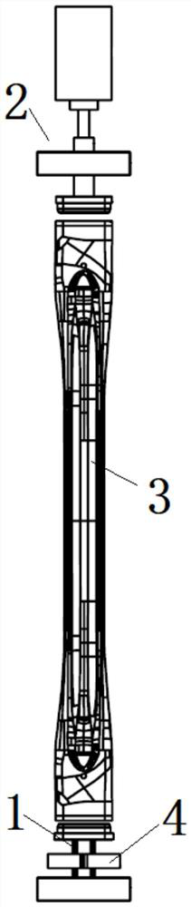
[0027] Such as figure 1 As shown, this embodiment provides a clamping device for high-frequency heat treatment process, including a lower positioning assembly 1 and an upper positioning assembly 2 arranged in the vertical direction, and the lower end of the length direction of the part to be processed 3 is placed on the lower positioning assembly. On the assembly 1, the ...


PUM


Abstract

The invention provides a clamping device for a high-frequency heat treatment process. The device comprises a lower positioning assembly and an upper positioning assembly which are arranged in a vertical direction, wherein the lower end of a to-be-treated part in a length direction is placed on the lower positioning assembly, the upper positioning assembly can adjust a fixing position in the vertical direction to clamp the upper end of the part, and an induction coil can move in the vertical direction to penetrate through the two ends of the part. The device has the advantages that the part is supported through the lower positioning assembly, and the upper positioning assembly is matched with the upper end of the part to enable the part to be kept vertical, so that the part does not bear too large pressure, arching deformation of the part is prevented, the part is not subjected to the effect of torsional force or pressure in a circumferential direction, and the torsional deformation of the part is reduced; and the induction coil can penetrate through the whole part, so that the part is integrally quenched, and the whole part can be subjected to heat treatment.

Description

technical field [0001] The invention relates to the technical field of heat treatment, in particular to a clamping device and method for a high-frequency heat treatment process. Background technique [0002] As the lightweight goal of automobile manufacturers is getting higher and higher, components with light weight and high strength have become the development trend of the automobile industry. The high-frequency heat treatment process uses a high-frequency induction coil to heat the part to about 900 ° C, and then cools the part with a quenching liquid to eliminate the stress concentration generated during the forming process, improve the overall strength of the part, and the fatigue resistance of the part Require. At present, most of the high-frequency heat treatment is positioned at one end, or the parts are directly placed on the tooling made of high-temperature resistant materials such as ceramics. During the heat treatment process, the parts undergo complex comprehen...

Claims


Application Information

Patent Timeline
Patent Type & Authority Applications(China)
IPC IPC(8): C21D1/667C21D1/42
CPCC21D1/667C21D9/0025C21D9/0018C21D9/0062C21D1/42Y02P10/25
Inventor 熊宜谋徐炎张俨
Owner 保隆沙士基达(安徽)液压成型有限公司
Why Eureka
Try Eureka