Aircraft Electrically-Assisted Propulsion Control System

a control system and electrically assisted technology, applied in efficient propulsion technologies, machines/engines, transportation and packaging, etc., can solve the problem of ineffective cooling effect, reduce the flow of combustion products, reduce the amount of fuel consumed, and reduce the effect of combustion product flow

Active Publication Date: 2018-06-28
ROLLS ROYCE PLC
View PDF7 Cites 52 Cited by
  • Summary
  • Abstract
  • Description
  • Claims
  • Application Information

AI Technical Summary

Benefits of technology

[0012]The controller may reduce the flow of combustion products produced by the engine core to mitigate or suppress the creation of a contrail.
[0013]The controller may increase the power / torque supplied to the propulsive fan by the electric motor during contrail mitigation. The controller may increase / control the rotational velocity of the propulsive fan via the electric motor during contrail mitigation.
[0014]The controller may control operation of the electric motor so as to meet a thrust demand for the aircraft. Where the flow rate of combustion products is reduced by lowering the rate of fuel burn in the engine core this may reduce torque and / or thrust generated by the engine core. The reduced torque and / or thrust may be mitigated by increasing the torque applied to one or more propulsive fan by the electric motor.

Problems solved by technology

During the night, however, the cooling effect is not operative.

Method used


Image

  • Aircraft Electrically-Assisted Propulsion Control System
  • Aircraft Electrically-Assisted Propulsion Control System
  • Aircraft Electrically-Assisted Propulsion Control System

Examples


Embodiment Construction

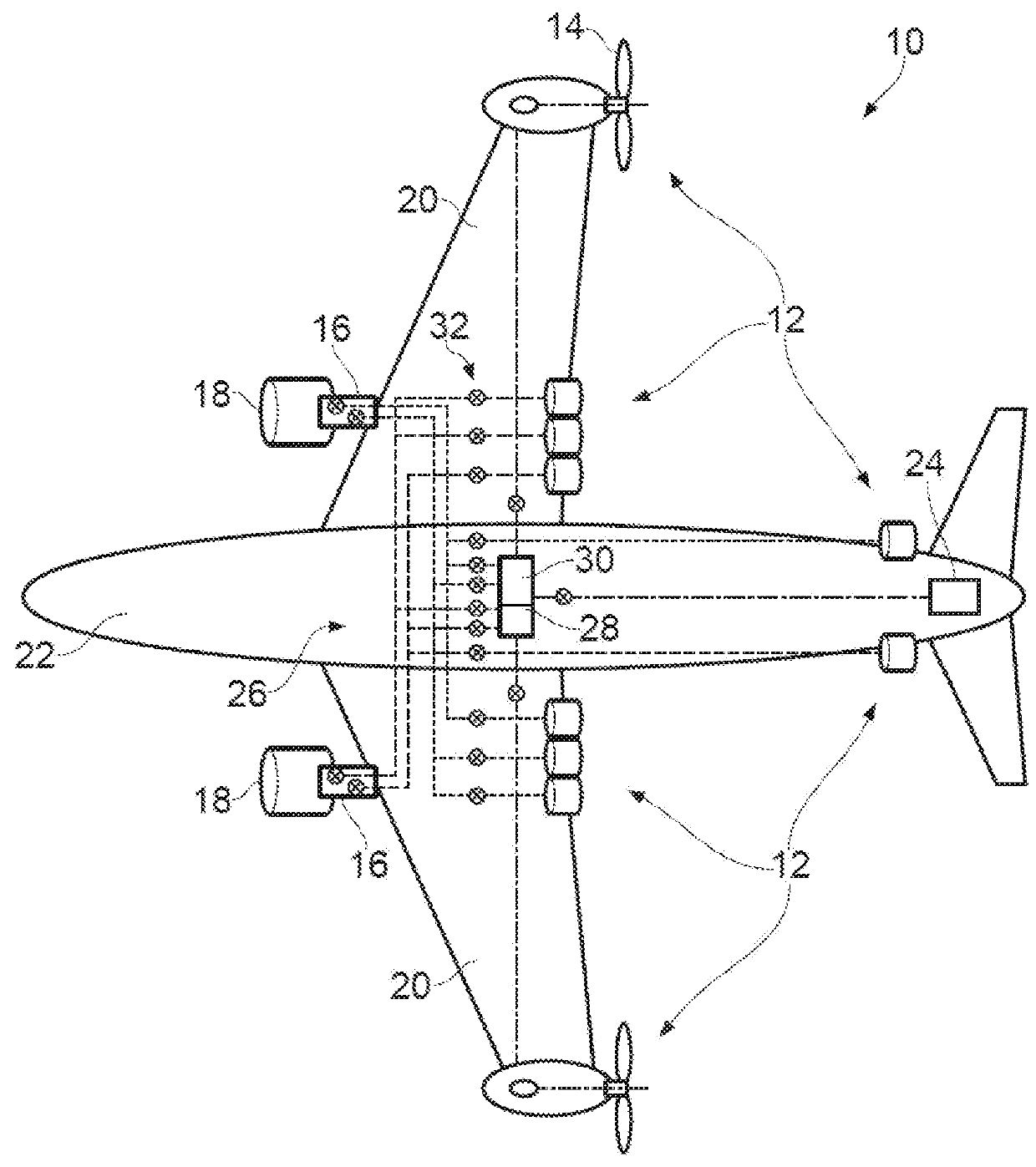
[0043]In FIG. 1 there is shown a schematic representation of an aircraft having an electrically assisted propulsive system 10 according to an example of the present invention. Although the rest of the description is mostly directed to aircraft having distributed propulsion units it will be appreciated that distributed propulsion systems provide just one context in which the invention may be used and aircraft without distributed propulsion may also operate in accordance with aspects of the invention described herein.

[0044]The electrical propulsive system 10 includes a plurality of electrical propulsive units in the form of fans 12 which are rotatably driven by electrical machines, for example superconducting electrical machines.

[0045]Each of the fans 12 includes a rotor having fan blades 14 mounted on a rotatable hub and may have a blade pitch adjustment mechanism for synchronously adjusting the pitch of the blades 14 relative to the air flow which passes them in use. Although only t...


PUM


Abstract

This invention concerns an aircraft propulsion system in which an engine has an engine core comprising a compressor, a combustor and a turbine driven by a flow of combustion products of the combustor. At least one propulsive fan generates a mass flow of air to propel the aircraft. An electrical energy store is provided on board the aircraft. At least one electric motor is arranged to drive the propulsive fan and the engine core compressor. A controller controls the at least one electric motor to mitigate the creation of a contrail caused by the engine combustion products by altering the ratio of the mass flow of air by the propulsive fan to the flow of combustion products of the combustor. The at least one electric motor is controlled so as to selectively drive both the propulsive fan and engine core compressor.

Description

CROSS-REFERENCE TO RELATED APPLICATION[0001]This specification is based upon and claims the benefit of priority from UK Patent Application Number 1622012.1 filed on 22 Dec. 2016, the entire contents of which are incorporated herein by reference.BACKGROUND OF THE INVENTION1. Field of the Disclosure[0002]The present disclosure concerns aircraft propulsion systems in which electrical energy is used to supplement the operation of a combustion engine. The invention particularly concerns methods for aiding in the control of the negative climate impact resulting from operation of a combustion engine, for example via vapour trail formation.2. Description of the Related Art[0003]Vapour trails, also known as condensation trails or contrails, are line-shaped ice clouds that appear behind aircraft under certain circumstances. The formation of a contrail depends on a number of factors, including: ambient temperature, humidity and pressure; the efficiency of the aircraft's engines; and the proper...

Claims


Application Information

Patent Timeline
Patent Type & Authority Applications(United States)
IPC IPC(8): B64D27/24B64D31/06F02C9/48
CPCB64D27/24B64D31/06F02C9/48B64D2027/026B64D2041/002F05D2220/50F05D2270/08F05D2270/311F05D2270/312F05D2270/313F05D2270/081F02K5/00F02C9/54F05D2220/76Y02T50/60F01D15/10F02C6/14F02C9/18
Inventor SWANN, PETERFLETCHER, PAULPELLEGRINI, ALVISEKULATHASAN, ASHOG
Owner ROLLS ROYCE PLC
Why Eureka
Try Eureka