Turret rock bolter with stinger/centralizer

Inactive Publication Date: 2002-07-02
J H FLETCHER & CO INC
View PDF5 Cites 48 Cited by
  • Summary
  • Abstract
  • Description
  • Claims
  • Application Information

AI Technical Summary

Benefits of technology

When the rock drill and the bolt driver are mounted on carriages which serve to move the rock drill and the bolt driver along their respective feed tracks, these carriages can be activated by a common carrier activation means which is shared between the two carriages. The selective activation of the carriage for the tool which is aligned with the work axis (the active tool) can be accomplished by immobilizing the carrier which resides off the work axis (the non-active tool). For this reason, it is preferred that a carriage stop member be attached to the base. The carriage stop member has a drill carriage disabling surface positioned to engage the drill carriage when the drill is the non-active tool, this engagement preventing advancement of the carriage along the drill feed track. Similarly, the carriage stop member has a bolt driver carriage disabling surface positioned to engage the bolt driver carriage when the bolt driver is the non-active tool and prevent advancement

Problems solved by technology

One of the problems with bolt setting is locating the hole which has been drilled.
One difficulty with these types of bolt aligning systems is that of accurately positioning the centralizer with respect to the hole into which the bolt is to be set.
Another complicating factor in drilling holes and inserting bolts into a rock surface is that frequently the rock surface into which bolts are being set is uneven.
This severely limits the ability to position the rock bolter in close proximity to the rock surface and limits the work space available for movement of components of the rock bolter which reside near the rock surface when the rock bolter is positioned to set bolts.
While this approach reduces the space required by the rock bolter in the vicinity of the rock surface, one difficult

Method used


Image

  • Turret rock bolter with stinger/centralizer
  • Turret rock bolter with stinger/centralizer
  • Turret rock bolter with stinger/centralizer

Examples


Embodiment Construction

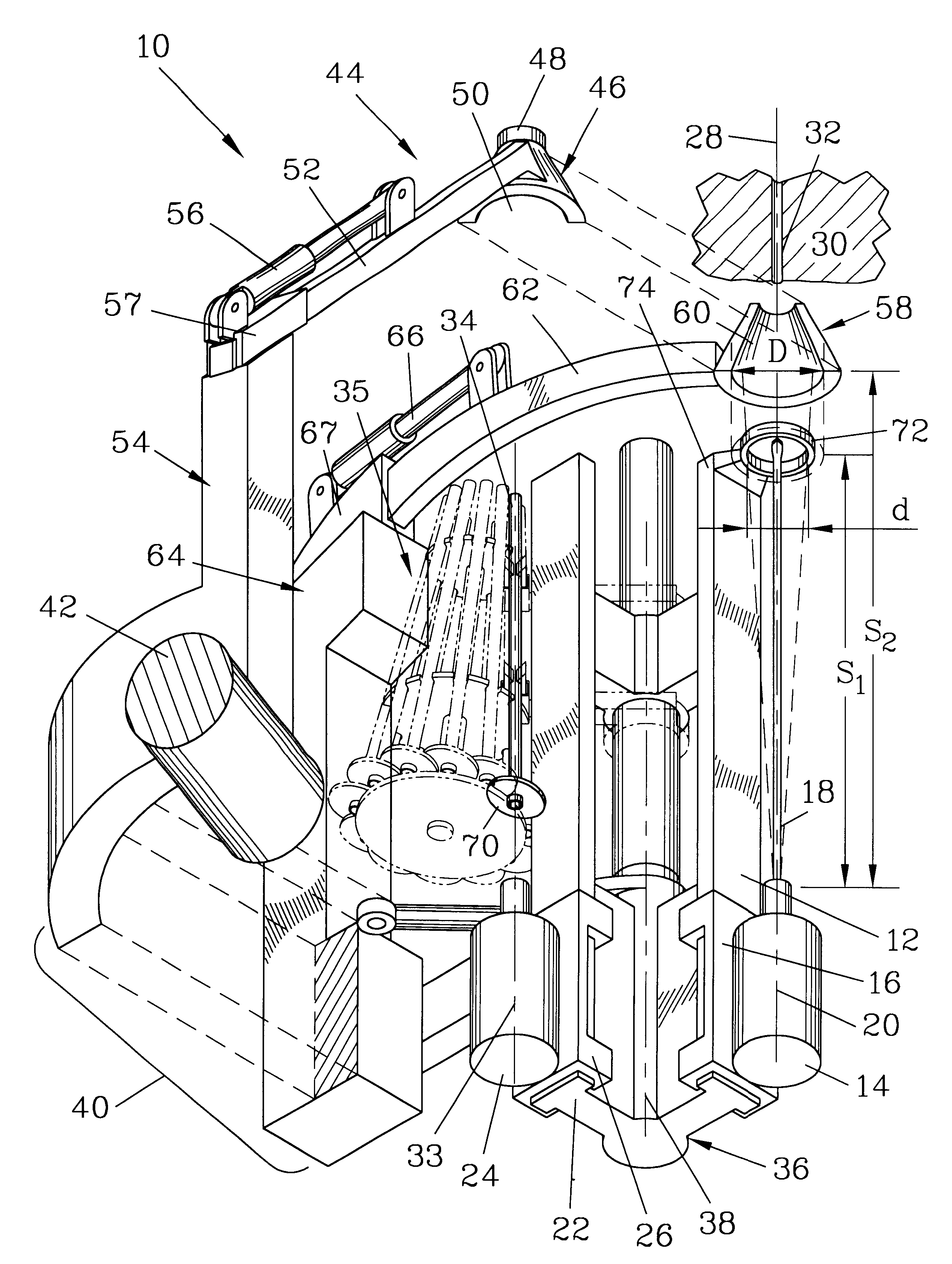
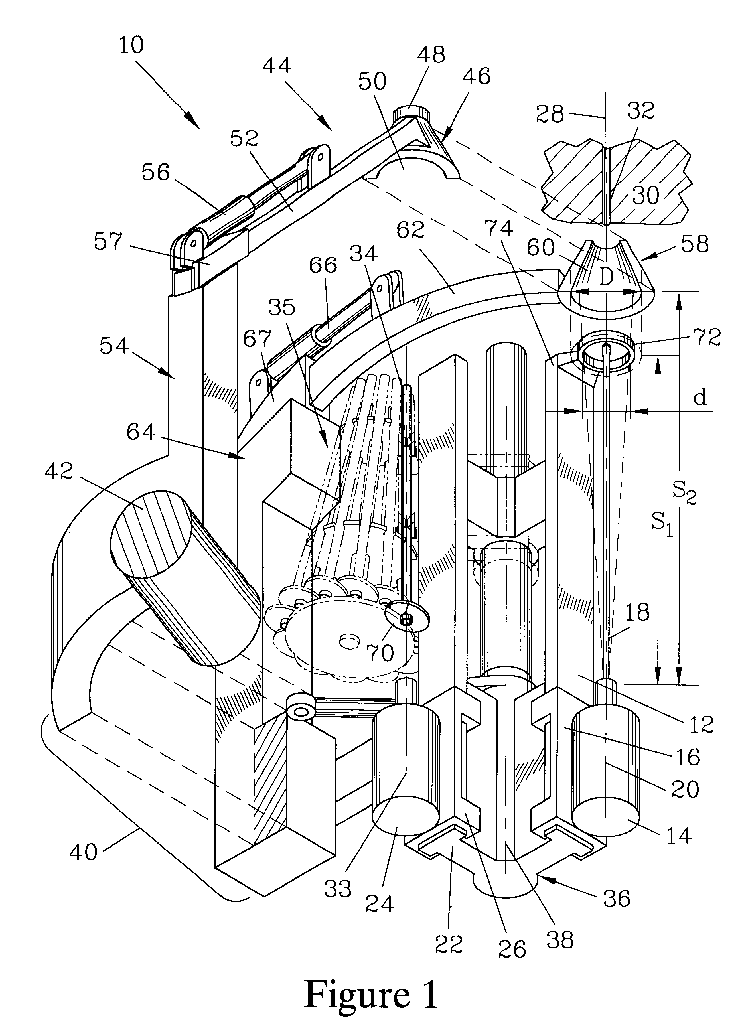
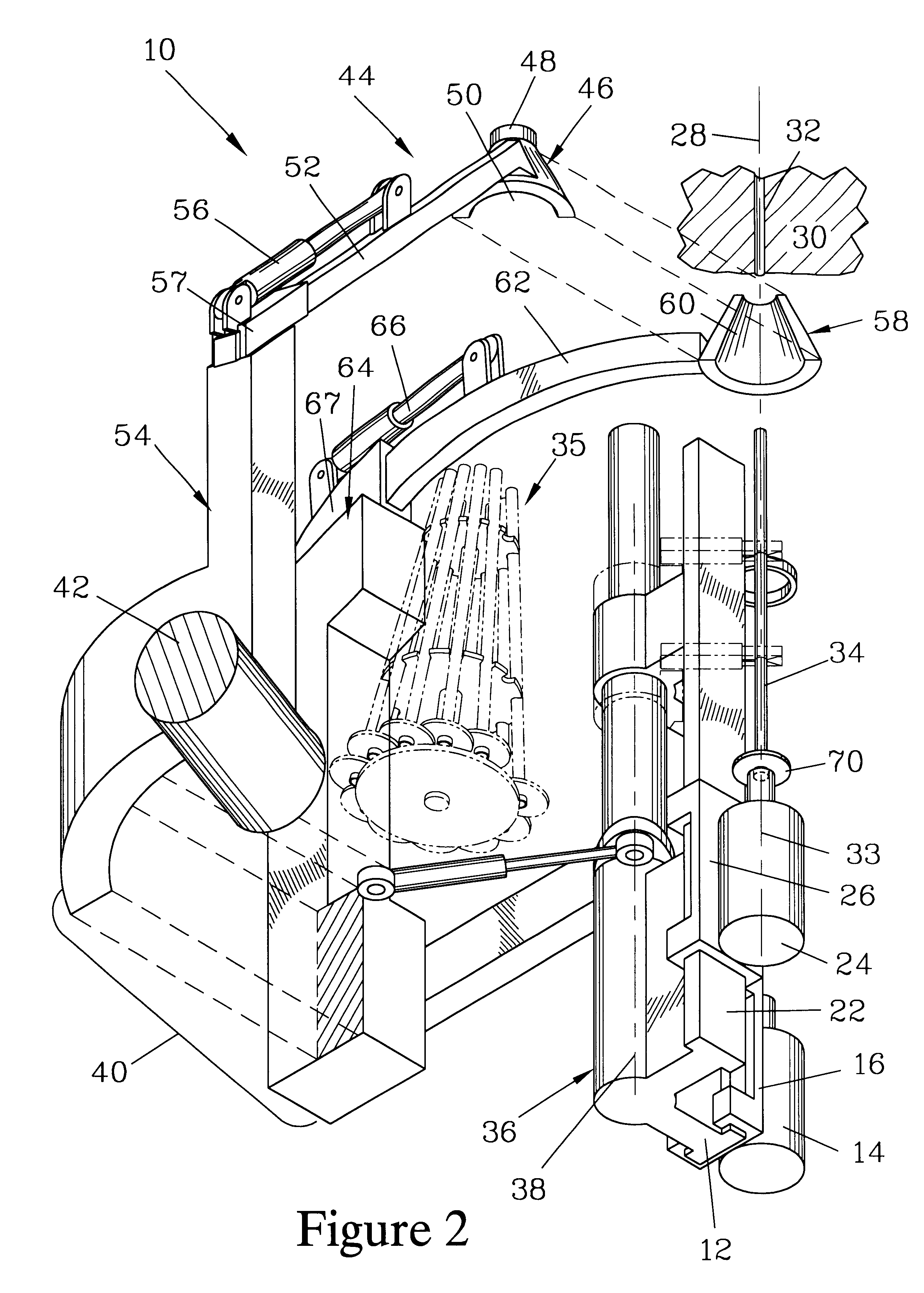
FIGS. 1 and 2 are partially exploded isometric views of one embodiment of a rock bolter 10 of the present invention. Both views illustrate a drill feed track 12, along which a drill 14 mounted on a drill carriage 16 can be slidably advanced. The drill 14 is fitted with a drill steel 18 (shown in FIG. 1) which is substantially aligned with a drill axis 20. Also shown in both views is a bolt driver feed track 22, along which a bolt driver 24 mounted on a bolt driver carriage 26 can be slidably advanced. FIG. 1 illustrates the rock bolter 10 with the drill feed track 12 in a work position where the drill steel 18 and drill axis 20 are aligned with a work axis 28 along which the drill steel 18 is advanced into a rock surface 30 to drill a bolt hole 32. FIG. 2 illustrates the rock bolter 10 in its alternate position where the bolt driver feed track 22 is in the work position, where a bolt driver axis 33 of the bolt driver 24 is aligned with the work axis 28. When so positioned, the bolt ...


PUM

PropertyMeasurementUnit
Stabilityaaaaaaaaaa

Abstract

A rock bolter has a drill and a bolt driver, both mounted to a turret that rotates relative to a base to align either the drill or the bolt driver with a work axis. A stinger/centralizer has two head elements, each advanced along a curvilinear path. When advanced, the head elements mate to provide a centralizer passage on the work axis. A supplementary stinger affixed to the base extends to engage the rock surface and provide stability as the head elements are retracted. The drill and the bolt driver are mounted on carriages activated by a common mechanism. A drill carriage disabling surface is affixed to the base to block the drill carriage when the drill is off the work axis, and a bolt driver carriage disabling surface is affixed to the base to block the bolt driver carriage when the bolt driver is off the work axis.

Description

The present invention relates to a rock bolting device for drilling holes and setting bolts into the drilled holes. More particularly, it is for a rock bolter having dual feed tracks which are mounted on a turret which selectively rotates the feed tracks to a work position where they are sequentially utilized for bolt hole drilling and bolt setting.A variety of rock bolters have been developed to drill holes and set bolts to stabilize rock walls. These rock bolters can be subdivided into single feed track and dual feed track rock bolters. U.S. Pat. No. 5,114,279 discloses a single feed shell rock bolter where a rock drill and a bolt driver are sequentially fed on to the feed track, which forms a work position for the rock drill or the bolt driver. Either the rock drill or the bolt driver, depending on which is positioned on the feed shell, can be advanced to a rock surface into which a bolt is to be set. U.S. Pat. Nos. 4,473,325 and 4,497,378 disclose a dual feed track rock bolter. ...

Claims


Application Information

Patent Timeline
IPC IPC(8): E21D20/00
CPCE21D20/006Y10T29/53478
Inventor COOMBS, PERRY L.BIGONEY, PAUL R.MORRISON, WARD D.
Owner J H FLETCHER & CO INC
Why Eureka
Try Eureka