
Railway vehicle and window thereof

A railway vehicle and vehicle window technology, which is applied in the direction of window/door frame, window glass installation, wing frame and other directions, can solve the problems of inability to look out, unable to meet the visual lookout requirements of special vehicles, and small space for turning inwards.

Active Publication Date: 2015-06-24
CRRC TANGSHAN CO LTD
View PDF5 Cites 1 Cited by
  • Summary
  • Abstract
  • Description
  • Claims
  • Application Information

AI Technical Summary

Problems solved by technology

[0006] There are at least the following problems in the above-mentioned up and down sliding open car windows: When the staff observes outward through the fixed sash at the lower part, taking a standard car window with a width of 1000 mm as an example, the shortest distance between the viewpoint and the car window is limited by its own physiological structure. about 60mm
Although the upper part of the inward-turning open window is a movable window, there is very little space for inward-turning, and it is impossible to look out of the car through the probe
[0009] There are at least the following problems in the above-mentioned inward-turning open car window: When the staff observes outward through the fixed sash in the lower half, taking a standard car window with a width of 1000mm as an example, the viewpoint is the closest to the car window due to the limitation of its own physiological structure. The distance is about 60mm
Under such observation conditions, the observation angle of the inward-turning open window is about 160 degrees, which is too small to meet the visual observation requirements of special vehicles
In addition, due to the limitation of the viewing angle of the inward-turning windows, it is necessary to install 10 inward-opening windows on both sides of the special railway vehicles to make up for the lack of viewing angles caused by poor viewing conditions.

Method used


Image

  • Railway vehicle and window thereof
  • Railway vehicle and window thereof
  • Railway vehicle and window thereof

Examples


Embodiment Construction

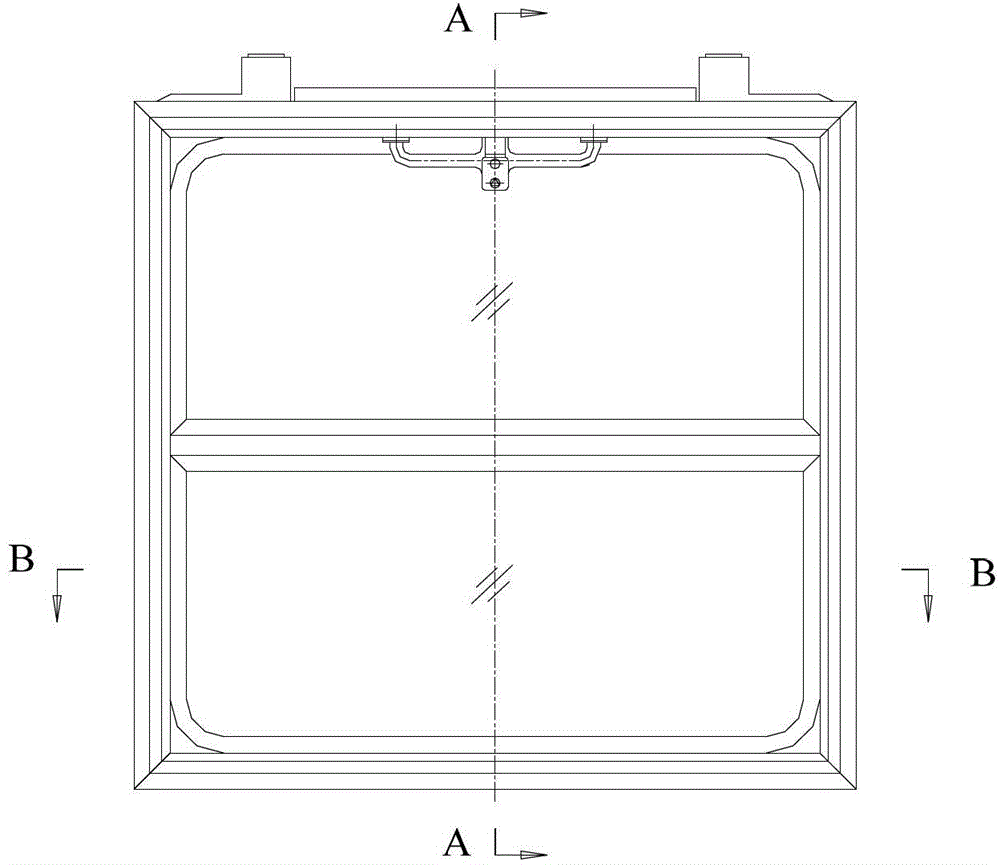
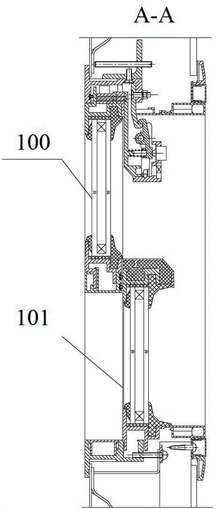
[0059] image 3It is a top view schematic diagram of vehicle window installation provided by the embodiment of the present invention, Figure 4 for image 3 Schematic diagram of the front view of the middle car window, Figure 5 for Figure 4 E-E to the sectional view, Figure 6 for Figure 4 The F-F to sectional view, Figure 7 for Figure 5 The partial enlarged schematic diagram of G, Figure 8 for Figure 5 The partial enlarged schematic diagram of H, Figure 9 for Figure 6 The partial enlarged schematic diagram of I, Figure 10 for Figure 6 Partial enlarged schematic diagram of J, Figure 11 It is a schematic diagram of the visual viewing angle of the window shown in 4.

[0060] Embodiments of the present invention provide a window 10 for railway vehicles, see image 3 , Figure 4 , Figure 5 and Figure 11 , which includes frames and forms. The frame body has an outer frame 1 and a mullion 2, the outer frame 1 protrudes as a whole, and each corner of t...


PUM


Abstract

The invention provides a railway vehicle and a window thereof. The window comprises a frame and a window body. The frame comprises an outer frame and vertical bars. The outer frame projects out. The vertical bars are disposed at corners of the outer frame to divide the frame into a plurality of sash frames having blunt included angles. The window body comprises glass members and two retainer plates. The glass members are as many as the sash frames. The glass members are fixed between the frame and the vertical bars or between the vertical bars. The retainer plates are fixed on the upper and lower surfaces of the outer frame respectively. When the window which projects out is in use, objects to be detected right in front of people can be seen through the glass members, the objects to be detected lengthwise along a vehicle body can also be seen, the visual angle is enlarged greatly, and accordingly opening the window or stretching the head out of the window is avoided and using safety is guaranteed.

Description

technical field [0001] The invention relates to mechanical technology, in particular to a window for a railway vehicle and a railway vehicle. Background technique [0002] In addition to the basic passenger vehicles used for passenger transportation, railway vehicles also have another type of special railway vehicles that implement detection and inspection functions for railway line facilities, such as track inspection vehicles, catenary inspection vehicles, infrared inspection vehicles, and tensile test vehicles. car etc. This type of special railway vehicle is used to detect and inspect railway line facilities during the dynamic operation of the vehicle. When the relevant personnel work in the car, on the one hand, they need to use special equipment for automatic detection, and on the other hand, they also need to observe and look out at the lines outside the car and its ancillary facilities through the windows on the side of the car. [0003] At present, the windows on ...

Claims


Application Information

Patent Timeline
Patent Type & Authority Patents(China)
IPC IPC(8): E06B1/36E06B3/06E06B3/64
Inventor 徐晓刚刘利雷赵凤启刘学颖贾红艳
Owner CRRC TANGSHAN CO LTD
Learn More