Air-suction type impeller case

An impeller, air suction technology, applied in mechanical equipment, non-variable volume pumps, machines/engines, etc., can solve problems such as insufficient scope, inability to maximize the use of impellers, low energy conversion rate, etc., to ensure the use of life, improve the effective utilization rate, and protect the effect of the impeller structure

Inactive Publication Date: 2013-09-11
DEYANG JINGNONG MACHINERY
View PDF5 Cites 2 Cited by
  • Summary
  • Abstract
  • Description
  • Claims
  • Application Information

AI Technical Summary

Problems solved by technology

Therefore, under the rotation of the impeller with the same function, the suction force of the air outlet of the traditional structure of the suction box is obviously not as large as that of the center of the impeller, and the negative pressure of the impeller rotation and the energy of the rotating wind flow cannot be used to the maximum extent. Substances that do not form hard impact and entanglement on the impeller, such as water flow and tiny objects, are obviously not widely used.

Method used


Image

  • Air-suction type impeller case
  • Air-suction type impeller case
  • Air-suction type impeller case

Examples


Embodiment

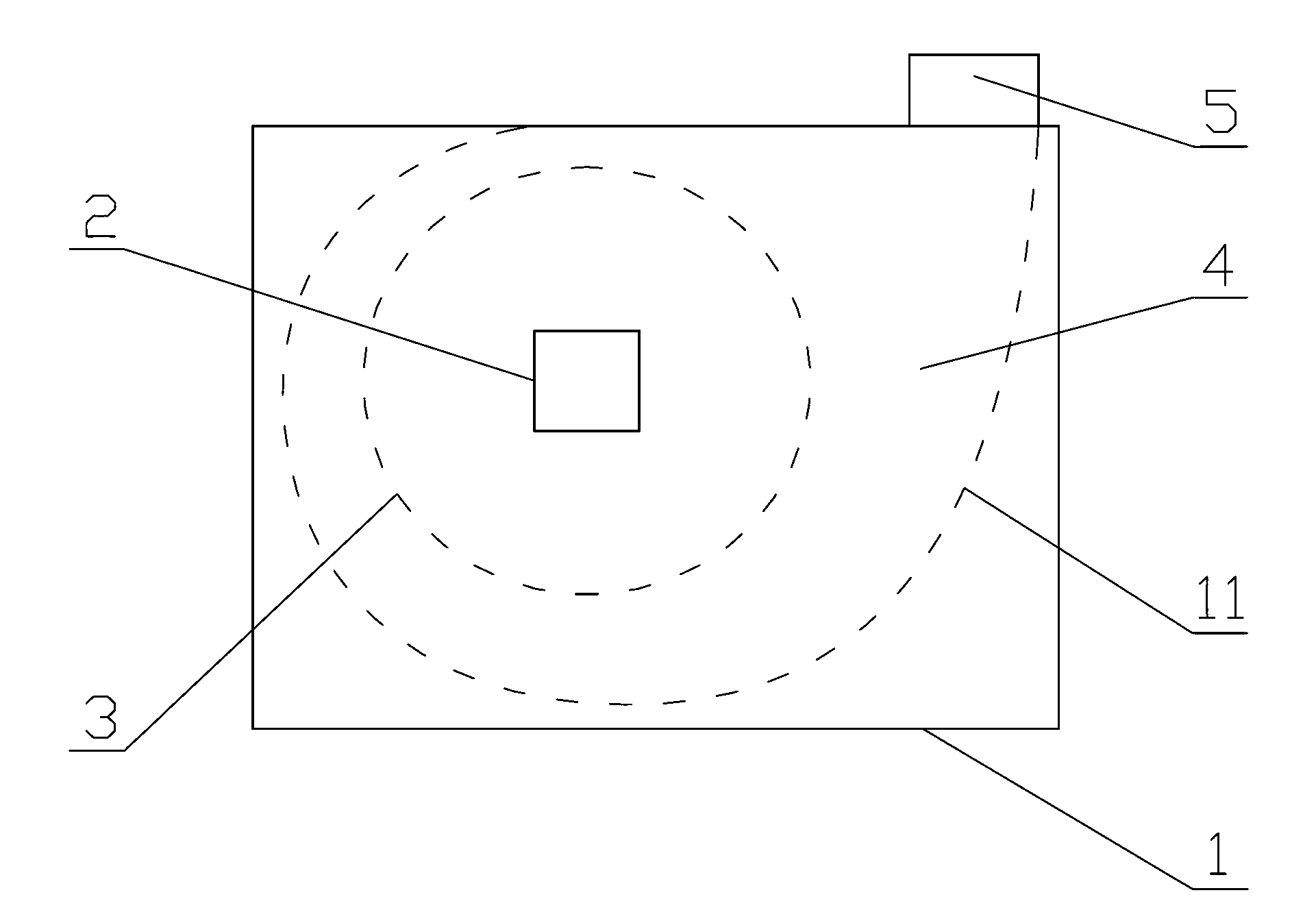
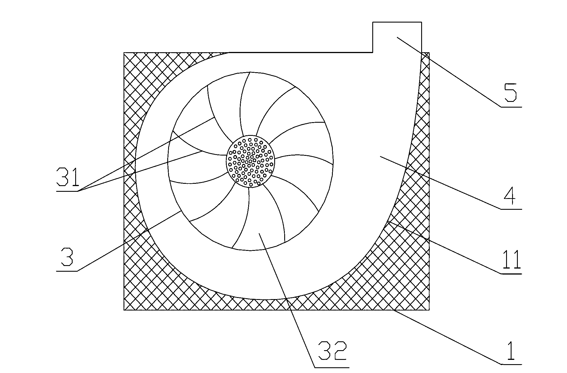
[0026] Such as Figure 1 ~ Figure 2 As shown, an air suction type impeller case mainly consists of a case case 1 and an impeller 3 arranged in an internal cavity of the case case 1. The outer wall of the case case 1 is provided with an inlet 2 communicating with its internal cavity. 2 The port of the internal cavity of the case shell 1 is located at the center of the impeller 3. In this way, the inlet of the casing 1 is attracted by the wind of the impeller 3, and the material (when used for picking cotton, the material is cotton) follows the wind from the inlet directly to the center of the impeller 3. Because the inlet 2 is located at the center of the casing 1. The port is at the center of the impeller 3, so that the rotating wind force of the impeller 3 is fully utilized, so that the effective wind suction force is the largest, and the wind is sucked in through the optimal position, so the rotating wind force of the impeller 3 is utilized to the maximum efficiency.

[0027] ...


PUM


Abstract

The invention discloses an air-suction type impeller case. The air-suction type impeller case mainly comprises a case shell and an impeller arranged in an inner cavity of the case shell, an inlet communicated with the inner cavity is formed in the outer wall of the case shell, a port, in the inner cavity of the case shell, of the inlet is positioned at the center of the impeller, and an outlet of the case shell is formed in the case shell along a tangential direction of the impeller. The inlet is formed right opposite to the center of the impeller inside the case shell, air pressure at the center of the impeller is low, and negative pressure at the center of the impeller is high, so that the maximum negative pressure position and the maximum rotary air flow position of the rotating impeller can be fully utilized, utilization rate of the air flow is maximized, air inflow suction force at the inlet is maximized, and effective utilization rate of air energy is increased. Meanwhile, the impeller has a function of separating air from other sucked articles, so that other large articles are prevented from being sucked in to wind and block the impeller, the impeller structure is protected under the condition that solid articles are sucked into a fan, and applicable range of the fan is enlarged.

Description

Technical field [0001] The invention relates to a suction box with an impeller, in particular to an air suction type impeller case. Background technique [0002] The suction box rotates in the box through the impeller and generates negative pressure and rotating air flow, thereby forming a large suction force to the outside to achieve the purpose of attracting outside air and solid materials. The traditional suction box mainly uses the negative pressure formed by the internal rotating air flow, and the use function is relatively single. Therefore, the suction port is generally arranged at the bottom or side of the wind box, and the suction port is on the edge of the vortex, not at the center of the vortex formed by the rotation of the impeller. Therefore, under the rotation of the same function of the impeller, the suction force of the suction box of the traditional structure is obviously not as large as the center of the impeller, and the impeller rotating negative pressure and...

Claims


Application Information

Patent Timeline
Patent Type & Authority Applications(China)
IPC IPC(8): F04D29/42F04D29/28
Inventor 张长虹张勇廖惠勇张争鸣
Owner DEYANG JINGNONG MACHINERY
Why Eureka
Try Eureka