Pressure cylinder with floating piston rod

A floating piston and pressurized cylinder technology, applied in the field of pressurized cylinders, can solve the problems of high piston rod and cylinder barrel, difficult processing, and high probability of oil leakage, and achieve the effects of high pressurization efficiency and simple structure

Inactive Publication Date: 2013-09-11
WUXI INST OF COMMERCE
View PDF4 Cites 2 Cited by
  • Summary
  • Abstract
  • Description
  • Claims
  • Application Information

AI Technical Summary

Problems solved by technology

[0002] At present, the general pressurized cylinder is installed directly on the piston rod. The concentricity requirements of the piston rod and the cylinder barrel are relatively high, the processing is difficult, and the probability of oil leakage is also relatively high.

Method used


Image

  • Pressure cylinder with floating piston rod

Examples


Embodiment Construction

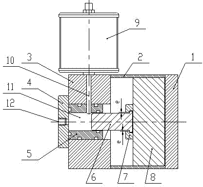
[0013] The present invention will be described in further detail below in conjunction with the accompanying drawings.

[0014] As shown in Figure 1, the floating piston rod booster cylinder includes rear end cover 1, cylinder barrel 2, front end cover 3, floating piston rod 6, piston rod fixing flange 7, piston 8 and oil cup 9, front end cover and rear end cover. The end caps are respectively covered on both sides of the cylinder, the cylinder is a hollow structure, a cavity is formed between the front end cover and the rear end cover, the cavity is a pressurized chamber, the piston is located in the cylinder, and one end of the floating piston rod The fixed flange of the piston rod is floatingly installed on the piston, and the size of the floating piston rod is smaller than the size of the fixed flange of the piston rod to realize the floating gap. One end of the pressurization chamber of the front end cover is covered with a gland flange 4, and the other end of the pressuri...


PUM


Abstract

The invention discloses a pressure cylinder with a floating piston rod. The pressure cylinder with the floating piston rod comprises a rear end cover, a cylinder barrel, a front end cover, the floating piston rod, a piston rod fixing flange, a piston and an oil cup, wherein the front end cover and the rear end cover respectively cover the two sides of the cylinder barrel, the cylinder barrel is of a hollow structure, a cavity is formed between the front end cover and the rear end cover, the cavity is a pressurizing cavity, the piston is arranged in the cylinder barrel, one end of the floating piston rod is installed on the piston through the piston rod fixing flange in a floating mode, a gland flange covers one end of the pressurizing cavity of the front end cover, the other end of the pressurizing cavity in the front end cover is sleeved at the other end of the floating piston rod, and is matched with the floating piston rod in a sealing mode, a through hole which is communicated with the pressurizing cavity is formed in the side wall of the front end cover, the oil outlet end of the oil cup is connected with the through hole, and an oil pressing opening which is communicated with the pressurizing cavity is formed in the gland flange. The pressure cylinder with the floating piston rod is simple in structure and easy to machine, improves efficiency, and solves the problems that leakage happens and machining is difficult due to decentration of piston rods of pressure cylinders.

Description

technical field [0001] This patent relates to a booster cylinder, in particular to a piston rod booster cylinder. Background technique [0002] At present, the general pressurized cylinder is directly installed on the piston rod. The concentricity requirements of the piston rod and the cylinder barrel are relatively high, the processing is difficult, and the probability of oil leakage is also relatively high. Contents of the invention [0003] The purpose of the present invention is to provide a floating piston rod booster cylinder, which can effectively solve the problem of oil leakage from the booster cylinder, reduce the difficulty of processing and assembly, have a simple structure, improve booster efficiency, and be easy to implement. [0004] Technical scheme of the present invention is: [0005] Floating piston rod pressurized cylinder, including rear end cover, cylinder barrel, front end cover, floating piston rod, piston rod fixing flange, piston, oil cup, front ...

Claims


Application Information

Patent Timeline
Patent Type & Authority Applications(China)
IPC IPC(8): F15B3/00F15B15/14
Inventor 王宝敏其他发明人请求不公开姓名
Owner WUXI INST OF COMMERCE
Why Eureka
Try Eureka