Pressurizing electromagnetic and pressurizing piezoelectric combined type gas jetting device

A technology of injection device and booster piezoelectric, which is used in oil supply devices, charging systems, combustion engines, etc., and can solve the problems of high gas injection control requirements, poor gas injection stability, and high pipeline structure requirements.

Active Publication Date: 2016-07-06
HARBIN ENG UNIV
View PDF4 Cites 2 Cited by
  • Summary
  • Abstract
  • Description
  • Claims
  • Application Information

AI Technical Summary

Problems solved by technology

[0003] The existing in-cylinder direct-injection gas injection devices mostly use high-pressure pumps to compress the gas to a specified pressure, and control the movement of the needle valve through a solenoid valve to realize gas injection. The transmission process from the terminal to the gas injection device has high requirements on the pipeline structure and serious gas leakage; the single-cylinder power coverage of the engine is large and the gas injection control requirements are high. The gas injection device with a large flow nozzle has a large gas injection volume, but the gas injection stability is poor and The control precision of small flow gas injection is low; while the injection device using small flow nozzles has high control accuracy for small flow gas injection, but it does not meet the demand for gas injection volume in the high-power working condition of the engine. Therefore, the gas injection device with a single nozzle is used The power of the matching engine is limited, and it cannot meet the requirements of engine gas injection control accuracy and power requirements under different working conditions at the same time; although the two gas injection devices can meet the requirements of engine gas injection, the size and installation position are limited by the cylinder head; The gas moving against the spool will intensify leakage to the solenoid valve end through the gap between the spool and the valve body, resulting in a decrease in gas injection pressure and injection rate, affecting engine power and fuel economy

Method used


Image

  • Pressurizing electromagnetic and pressurizing piezoelectric combined type gas jetting device
  • Pressurizing electromagnetic and pressurizing piezoelectric combined type gas jetting device
  • Pressurizing electromagnetic and pressurizing piezoelectric combined type gas jetting device

Examples


Embodiment Construction

[0023] The present invention will be further described below in conjunction with legend:

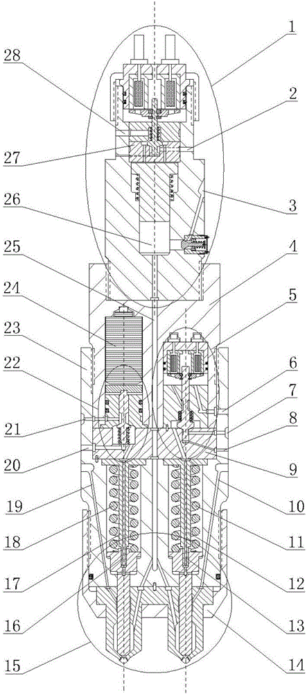
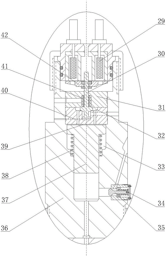
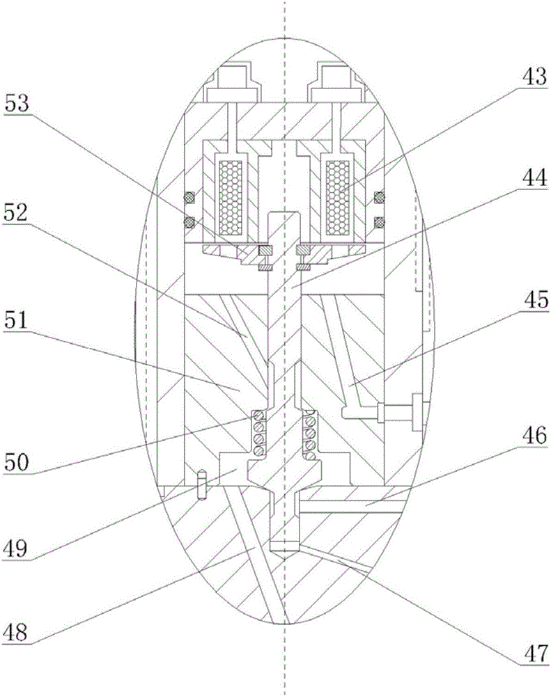
[0024] combine Figure 1-5 , The combined booster electromagnetic-supercharger piezoelectric gas injection device of the present invention mainly includes a gas booster part 1, an electromagnetic control part 5, a piezoelectric control part 22, a double gas nozzle part 15, a booster device housing 36, and a control device Shell 4, injection device shell 23, control valve base 9, air intake channel 25, pressurized oil inlet oil passage 2, pressurized oil drain oil passage 28, control oil inlet I7, control oil inlet II21, Control oil drain port I6, control oil drain port II20, seal oil inlet circuit I10, seal oil inlet circuit II19.

[0025] Gas booster part 1 is composed of air inlet 3, booster piston 37, booster piston upper cavity 39, booster piston lower cavity 26, booster piston return spring 38, booster piston return spring chamber 33, booster solenoid valve coil 29. Booster armatu...


PUM


Abstract

The invention provides a pressurizing electromagnetic and pressurizing piezoelectric combined type gas jetting device. An electromagnetic control part and a piezoelectric control part are arranged in a control device shell. A double-gas nozzle part is arranged in a jetting device shell. The lower end of a pressurizing device shell is connected with the upper end of the control device shell. The lower end of the control device shell is connected with the upper end of the jetting device shell, a control valve base is arranged between the double-gas nozzle part and the electromagnetic control part, and a control valve base is arranged between the double-gas nozzle part and the piezoelectric control part. The center of the pressurizing device shell, the center of the control device shell and the center of the jetting device shell are each provided with an air inlet channel, wherein the air inlet channels communicate with one another. The gas pressurizing efficiency is high, the gas jetting flexibility is high, the requirement for the large-range-power gas jetting amount and the requirement for jetting rule changeability of a system can be met, meanwhile, fuel is used for sealing gas, the problem that the gas leaks through valve needle couple parts can be well solved, and the dynamic property and the fuel economical efficiency of an engine can be effectively improved.

Description

technical field [0001] The invention relates to a dual-fuel engine gas injection device, in particular to a combined supercharged electromagnetic-supercharged piezoelectric gas injection device. Background technique [0002] The development of alternative fuels for engines is one of the very effective means to solve the problems of energy shortage and environmental pollution. Due to the advantages of abundant resources, low price and clean combustion, gaseous fuel has become an alternative fuel for engines with good development prospects. [0003] The existing in-cylinder direct-injection gas injection devices mostly use high-pressure pumps to compress the gas to a specified pressure, and control the movement of the needle valve through a solenoid valve to realize gas injection. The transmission process from the terminal to the gas injection device has high requirements on the pipeline structure and serious gas leakage; the single-cylinder power coverage of the engine is la...

Claims


Application Information

Patent Timeline
Patent Type & Authority Applications(China)
IPC IPC(8): F02M21/02
CPCF02M21/02F02M21/0248F02M21/0251F02M21/0263Y02T10/30
Inventor 范立云董晓露马修真李学民彭怀利董全
Owner HARBIN ENG UNIV
Why Eureka
Try Eureka