Weighing cell operating on the principle of magnetic power compensation with optoelectronic position sensor

A technology of compensation principle and electromagnetic force, which is applied in the direction of weighing equipment, weighing, and optical components using electromagnetic balance, and can solve problems such as increasing manufacturing costs

Active Publication Date: 2013-09-11
METTLER TOLEDO INC
View PDF9 Cites 10 Cited by
  • Summary
  • Abstract
  • Description
  • Claims
  • Application Information

AI Technical Summary

Problems solved by technology

Therefore it requires a certain product to adjust each unit individually during t

Method used


Image

  • Weighing cell operating on the principle of magnetic power compensation with optoelectronic position sensor
  • Weighing cell operating on the principle of magnetic power compensation with optoelectronic position sensor
  • Weighing cell operating on the principle of magnetic power compensation with optoelectronic position sensor

Examples


Embodiment Construction

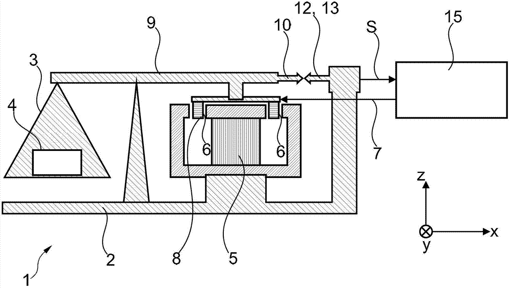
[0041] exist figure 1 A scale or weighing unit 1 with electromagnetic force compensation and photoelectric position sensor is schematically shown in . Add a Cartesian coordinate system as a reference for spatial orientation, the x and z axes of this coordinate system are located at figure 1 In the plane of the drawing, the y-axis points to the half-space behind the plane of the drawing. The shown components include: a fixed base part 2; a load receiver 3, which is constrained to the base part 2 for guided mobility and is used to receive the gravity of a weighing load 4; a cup-shaped permanent magnet system 5, which has an air gap 6 (in cross-sectional view), the system is rigidly mounted on the base part 2; a coil 8, which is movably suspended in the air gap 6 and directs the flow of a compensating current 7; and a force-transmitting mechanical connection 9 , which is located between the load receiver 3 and the coil 8, here shown in the shape of a balanced beam. Photoelectr...


PUM


Abstract

A weighing cell has a fixed base portion, a load receiver constrained to the base portion, a permanent magnet with air gaps, a coil hanged in the air gaps and guiding flowing of a compensation current, and a force transmission connection located between the load receiver and the coil. An optoelectronic position sensor includes a light source, a light receiver, and a shutter vane, wherein the shutter vane is connected to the connection, midpoints of the light source and the light receiver limit a light axis, the light source and the light receiver are arranged to be face to face opposite the gap, and the shutter vane is movably arranged at a shutter vane distance between the light source and the light receiver. The light receiver functions to generate a position sensor signal corresponding to a deflection of the shutter vane from a zero position which occurs as a result of placing a load onto a load receiver. A controller functions to regulate compensation current, the shutter vane and the movable parts of the weighing cell connected to the shutter vane are returned to the zero position by the electromagnetic force between a coil and permanent magnet system. The shutter vane distance is located at a sub-segment of the gap, and the sub-segment is adjacent to the light receiver and extends along the gap being not more than 1/3.

Description

technical field [0001] The invention relates to a scale or weighing unit which is based on the principle of magnetic compensation and which comprises an optoelectronic position sensor. Background technique [0002] The principle of electromagnetic force compensation is widely used in various weighing instruments used in commerce, industry and laboratories. This principle has the particular advantage that a weighing instrument of excellent measurement accuracy can be realized with it. Analytical scales based on the principle of electromagnetic force compensation have the ability, for example, to determine a weighing load of 100 grams with a measurement resolution of 0.01 milligrams, ie with an accuracy of one in ten million. [0003] The scale or weighing unit to which the present invention relates has: a fixed base part; a load receiver which is movably constrained to the base part and which is used to receive a weighing load; a permanent magnet system which is preferably m...

Claims


Application Information

Patent Timeline
IPC IPC(8): G01G7/02
CPCG01G7/04G01G7/045G01G7/02G02B6/4226G02B7/003G06F3/0304
Inventor C·贝甘T·克佩尔S·巴尔蒂斯伯格
Owner METTLER TOLEDO INC
Why Eureka
Try Eureka