A switch-over type control device for output power compensation

A technology for output power and control devices, which is applied in the direction of output power conversion devices, control/regulation systems, and conversion equipment with intermediate conversion to AC, and can solve problems such as aggravated output power differences

Inactive Publication Date: 2007-05-16
SYST GEN
View PDF0 Cites 39 Cited by
  • Summary
  • Abstract
  • Description
  • Claims
  • Application Information

AI Technical Summary

Problems solved by technology

[0017] Comparing the above equations (3) and (4), due to the transmission delay time t inside the PWM controller 1 d Will make the excitation current more than the theoretical value (V IN /L P ×t d , therefore, there will be a larger power limit voltage V at high input vol

Method used


Image

  • A switch-over type control device for output power compensation
  • A switch-over type control device for output power compensation
  • A switch-over type control device for output power compensation

Examples


Embodiment Construction

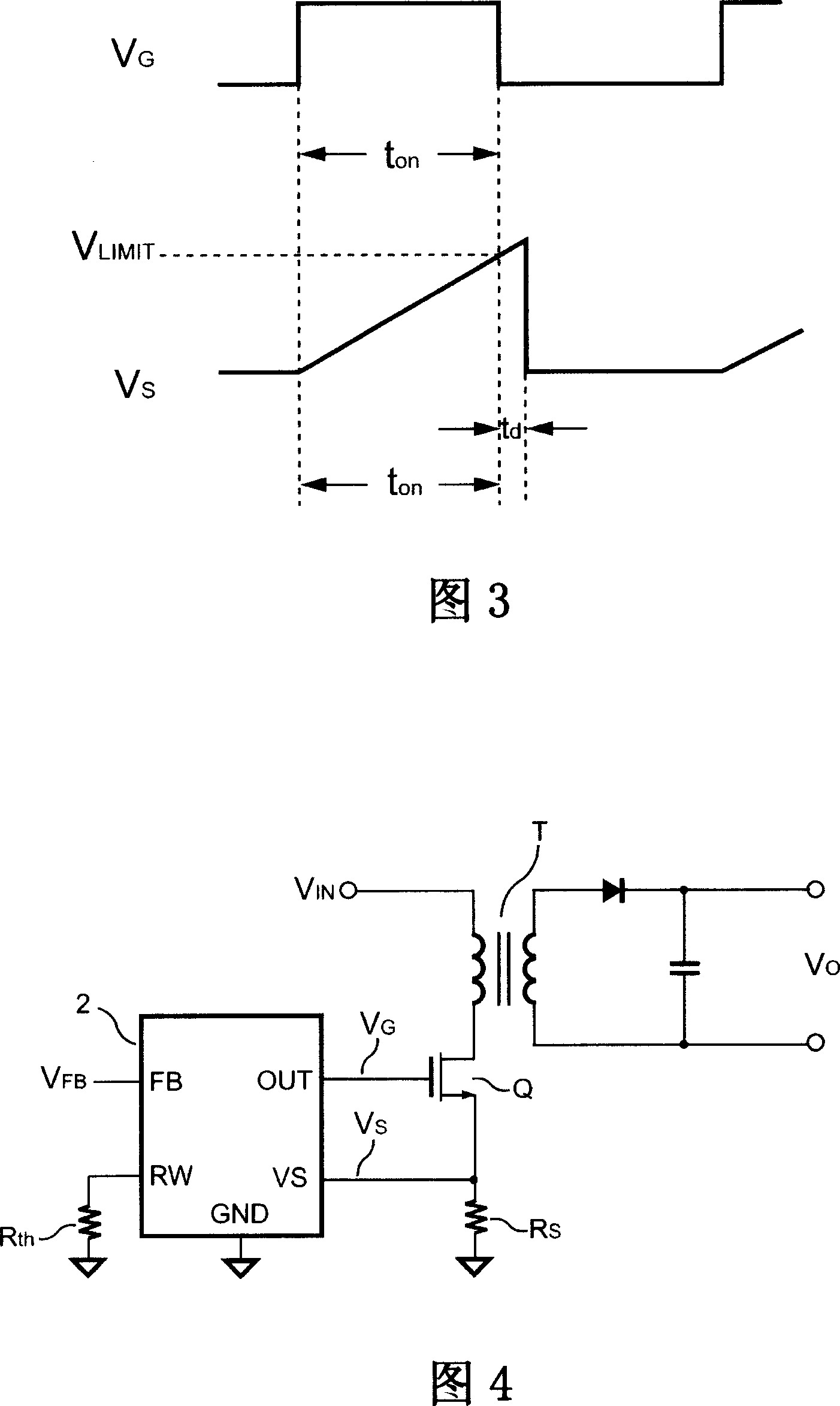
[0053] Please refer to FIG. 4 , which is a schematic diagram of a preferred circuit of the switching control device for output power compensation of the present invention used in a power supply. In the present invention, the switchable control device 2 that realizes output power compensation through impedance adjustment adjusts an impedance unit R according to th resistance, a voltage feedback signal V FB and from a sense resistor R S The current sense signal is obtained on V S , to determine the output drive signal V G The on-time of the drive signal V G The power switch Q is controlled to switch the transformer T to achieve the purpose of compensating the output power of the power supply.

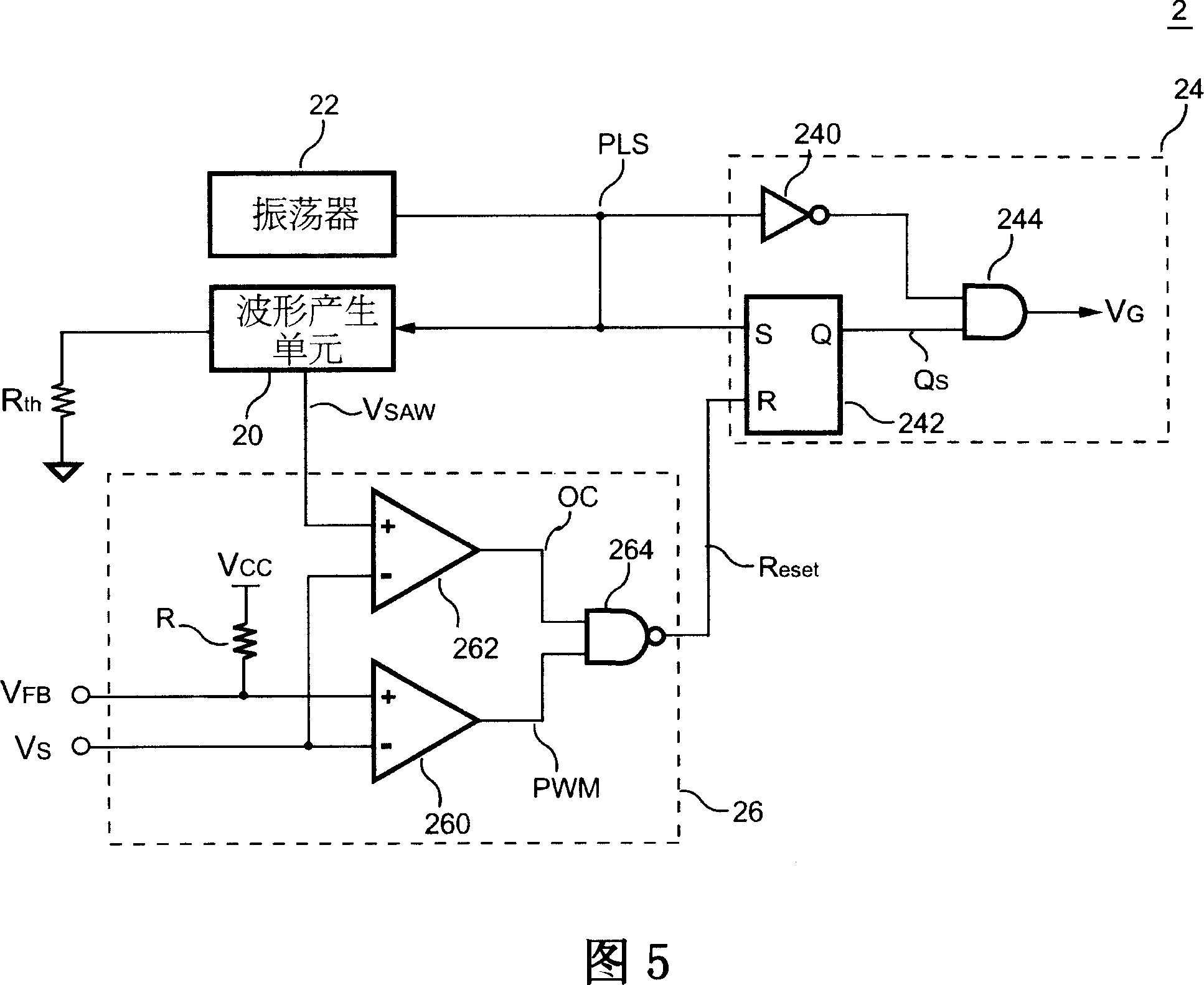
[0054] Referring to FIG. 4 , please refer to FIG. 5 , which is a schematic block diagram of a preferred circuit of the switchable control device for output power compensation of the present invention. The switching control device 2 for output power compensation is coupled to a magnet...


PUM


Abstract

The related switch controller for output power compensation comprises: an oscillator to output an impulse signal, a waveform generation unit to receive the impulse signal and output a power limit signal, an impedance unit to decide the slope of the limit signal, a comparison unit to output a reset signal, and an output unit to receive the reset signal and impulse signal and output a drive signal to the power switch. This invention can obtain same output power for different input power voltages.

Description

technical field [0001] The invention relates to a switchable control device for output power compensation through impedance adjustment, in particular to a switchable control device for output power compensation in a power supply by adjusting the resistance of an impedance unit. Background technique [0002] Pulse Width Modulation is an existing technique for controlling and stabilizing the output power of a power supply. The power supply must provide various protection functions, such as over-voltage, over-current and over-power protection. Overcurrent and overpower protection are used to protect the power supply and peripheral circuits to avoid permanent damage. In the over-power protection of the power supply, through the design of the output power compensation function, the power supply can have the same overload protection point under high and low input voltage. [0003] Please refer to FIG. 1 , which is a schematic diagram of a conventional power supply circuit. In t...

Claims


Application Information

Patent Timeline
IPC IPC(8): H02M3/28H02M3/335
Inventor 杨大勇
Owner SYST GEN
Why Eureka
Try Eureka