
Test Circuit for Switch Life

A technology for testing circuit and switch life, which is applied in the field of switching elements, can solve the problems that the accuracy of test data is difficult to be guaranteed, and the workload of experimenters is increased, and achieve the effects of simple structure, reduced working intensity and reliable work

Inactive Publication Date: 2016-06-22
OCEANKING DONGGUAN LIGHTING TECH +2
View PDF10 Cites 0 Cited by
  • Summary
  • Abstract
  • Description
  • Claims
  • Application Information

AI Technical Summary

Problems solved by technology

In the past, the life test of the number of switching operations was carried out. During the test, the experimenters needed to stop checking whether the switch was normal after switching the number of times at different stages in the middle of the test, which caused a corresponding increase in the workload of the experimenters, and it was difficult to guarantee the accuracy of the test data.

Method used


Image

  • Test Circuit for Switch Life

Examples


Embodiment Construction

[0013] In order to enable those skilled in the art to better understand the technical solution of the present invention, further detailed description will be given below in conjunction with the accompanying drawings and embodiments.

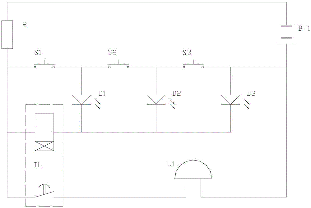
[0014] The basic composition of the test circuit for switch life of the present invention includes a switch to be tested, a power supply, a light display unit, a time relay, an audible alarm unit and a current limiting resistor.

[0015] Among them, the power supply, the current limiting resistor and several switches to be tested are connected in series to form a current loop; the input end of the light display unit is connected to an output end of the power supply, and the output end of the light display unit is connected in series to an input end of the time relay. The other input end of the relay is connected to the other output end of the power supply through a current limiting resistor; the sound alarm unit is connected in series with the out...


PUM


Abstract

The invention discloses a circuit for testing the service life of switches. According to the circuit for testing the service life of the switches, a power supply, a current-limiting resistor and the switches to be tested are connected into a current loop in series. The input end of a light display unit is connected to one output end of the power supply, the output end of the light display unit is connected to one input end of a time relay in series, and the other input end of the time relay is connected to the other output end of the power supply through the current-limiting resistor. After an audible alarming unit is connected with the output end of the time relay in series, the audible alarming unit is connected to two output ends of the switches to be tested in parallel, wherein the switches to be tested are connected in series. In the testing process of repeating switch-on and switch-off of the switches to be tested, when any one of the switches to be tested is switched off abnormally, a fault indicating lamp of the light display unit is on continuously, the output end of the time relay is conductive, the audible alarming unit is energized and gives an alarm, and a corresponding identification display lamp flickers or is off continuously. The accuracy of test data, obtained by the circuit, of the service life of the switches is high and work intensity of an experimenter is relieved.

Description

technical field [0001] The invention relates to the technical field of switch elements, in particular to the life test of switches. Background technique [0002] The function of the switch is to turn on and off. As an electronic component that can open the circuit, interrupt the current or make it flow to other circuits, it is widely used in lamps to turn on and off the lamps. [0003] The operating life of a switch is an important indicator of its quality. In the past, in the life test of the number of switching operations, the experimenters need to stop checking whether the switch is normal after switching the number of times at different stages during the test process, resulting in a corresponding increase in the workload of the experimenters, and it is difficult to guarantee the accuracy of the test data. Contents of the invention [0004] The technical problem to be solved by the present invention is to provide an audible alarm circuit for the switch life test in vie...

Claims


Application Information

Patent Timeline
Patent Type & Authority Patents(China)
IPC IPC(8): G01R31/327
Inventor 周明杰方璋
Owner OCEANKING DONGGUAN LIGHTING TECH
Learn More