Round smooth plating printing press and operating procedure of the same

A working method and technology of printing presses, which are applied in the directions of rotary flat presses, printing presses, printing, etc., can solve the problems of limited step distance between printing plates and printing plates, high cost, and the process cannot be carried out on the same machine at the same time, so as to shorten the time. Processing time, the effect of reducing production costs

Inactive Publication Date: 2008-02-27
佛山市顺德区容桂德胜印刷机械厂
View PDF0 Cites 0 Cited by
  • Summary
  • Abstract
  • Description
  • Claims
  • Application Information

AI Technical Summary

Problems solved by technology

In addition, the rolling speed of the roller must be controlled very precisely. If the speed is too fast, the printing material will be pushed, and if the speed is too slow, the printing material will be pulled.
[0003] The paper feeding method of the intermittent rotary machine is that during the printing process, the printing material is synchronously fed in the same direction between the two cylinders: when the printing plate cylinder turns to the preset rotation position, the printing material immediately returns in the reverse direction , this way of paper feeding is back and forth movement, and the printing material basically has no real interval and sufficient residence time in the movement, so this printing method can only be used for printing, and the flat die-cutting and other processes after printing cannot be carried out on the same machine at the same time conduct
[0004] Nowadays, the rotary flat printing machine that uses roll materials can only use the embossing method, and cannot use other printing methods. During printing, the printing plate cylinder can only move back and forth in the longitudinal direction of the printing machine. There are also certain restrictions on the step distance between versions
[0005] In addition, in the printing process of common offset printing machines, due to the use of ratchet mechanism or linkage mechanism to apply ink and back and forth printing of the rubber cloth cylinder, it is necessary to drive the motor forward and reverse or reverse the direction through an intermediate mechanism, which is difficult to achieve in actual production. High speed and high quality printing effect
[0006] If the die-cutting is carried out when the printing material is in motion, then the die-cutting must use a roller die-cutting knife. This kind of roller die-cutting knife is very expensive, and the second is that the specifications are too restrictive.

Method used


Image

  • Round smooth plating printing press and operating procedure of the same
  • Round smooth plating printing press and operating procedure of the same
  • Round smooth plating printing press and operating procedure of the same

Examples


no. 1 example

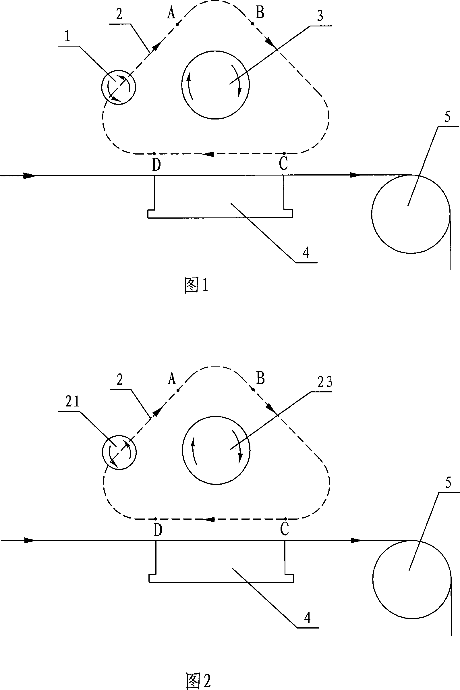
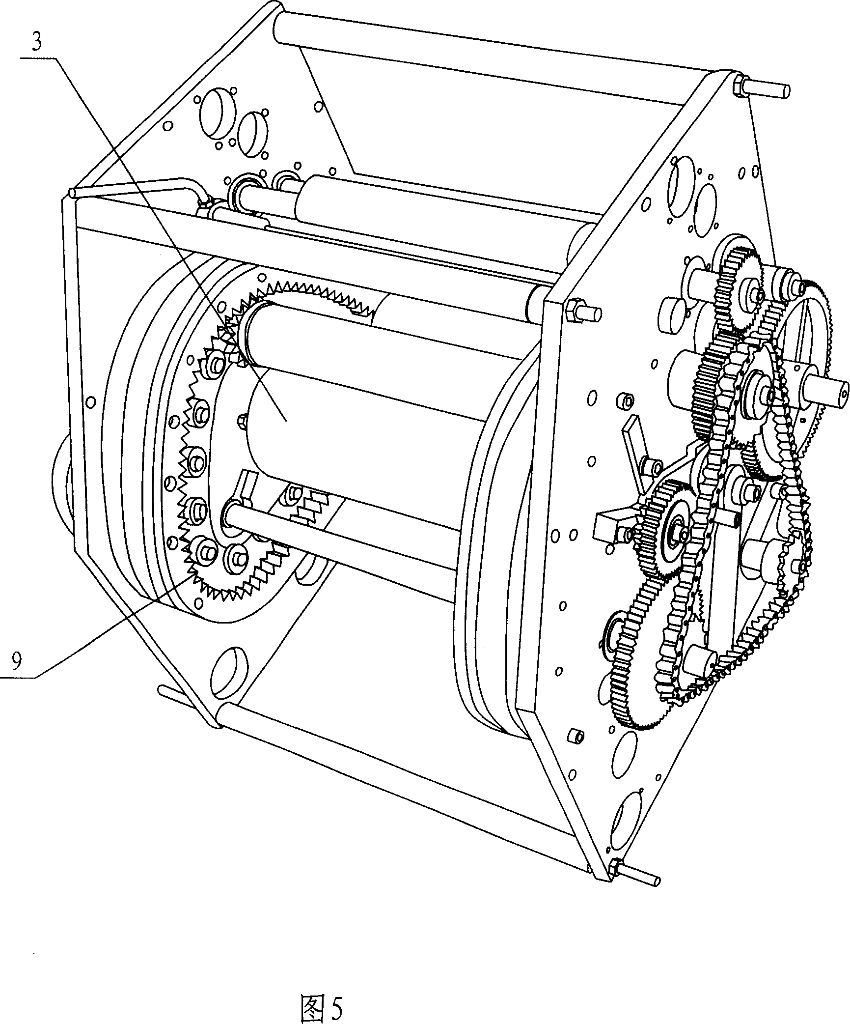
[0040] Referring to Fig. 1 and Fig. 4-Fig. 5, circular rails 2 are arranged symmetrically on the left and right sides of the circular flattening offset printing machine. The length of the arc-shaped ink section AB in the track 2 is equal to the circumference of the adhesive tape cylinder 1 , and the arc-shaped ink section AB is concentrically arranged with the printing plate cylinder 3 . The printing table 4 is arranged below the two rails 2, and the two ends of the printing plate cylinder 3 are respectively arranged in the middle of the left and right two rails. For transferring ink pattern or ink, the track 2 is provided with a straight printing section CD corresponding to the printing table 4 , and the length of the straight printing section CD is equal to the circumference of the printing plate cylinder 1 .

[0041] The track 2 is provided with a chain 7 connected to the output shaft of the drive motor, and the side of the track 2 is provided with an annular internal tooth...

no. 2 example

[0043] Referring to Fig. 2 and Fig. 10-Fig. 11, the plate cylinder 21 in the letterpress printing machine is arranged on the track 2, and the ink roller 23 is arranged in the middle of the track.

[0044] The rest are the same as the first embodiment and will not be repeated.

no. 3 example

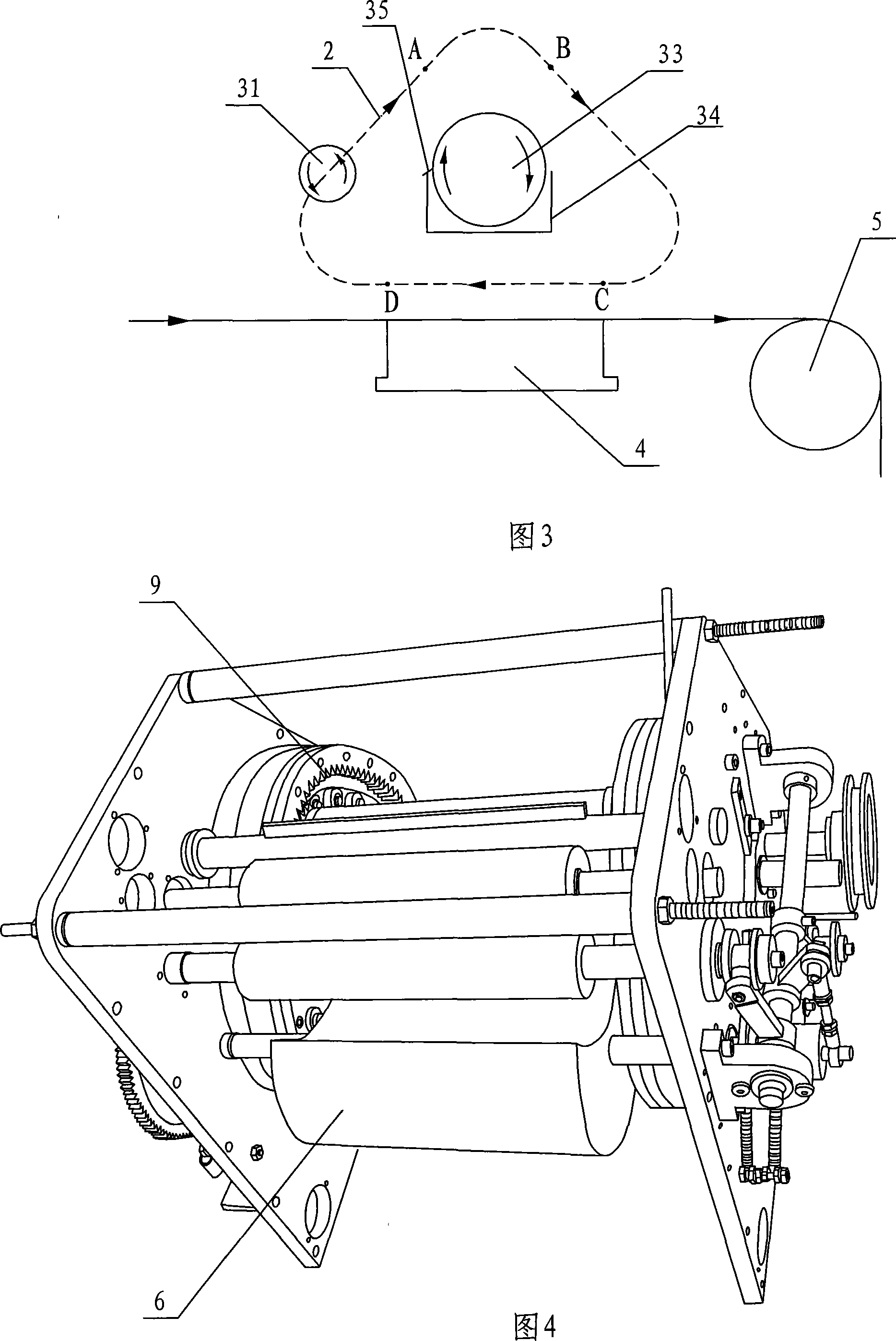
[0046] Referring to Fig. 3 and Fig. 10-Fig. 11, the plate cylinder 31 in the flexographic printing machine is arranged on the track 2, the anilox roller 33 is arranged in the middle of the track, the anilox roller is arranged in the ink tank 34, and the ink tank is provided with Squeegee 35, one end of the squeegee is in contact with the surface of the anilox roller.

[0047] The rest are the same as the first embodiment and will not be repeated.


PUM


Abstract

The invention relates to a round applanation printing machine, comprising printing roller, inking roller, printing platform and pulling material roller. Ring rail is set on the printing machine. Arc ink segment AB and straight printing segment CD are set in the rail. The printing roller is set on the rail and the inking roller is set in the middle of rail. When the printing roller is located in the arc ink segment AB the printing roller is pressed and connected with the surface of inking roller and ink patter or ink are printed. When the printing roller is located in the straight printing segment CD above the printing platform the printing roller is pressed and connected with the printing-carrier on the printing platform in the line-face contact way and ink pattern on it is printed on the printing carrier. The pulling material roller connected with printing carrier runs intermittently in one way. The invention is provided with simple and reasonable structure, high-speed printing roller in one way, intermittent running of pulling material roller in one way, line-face contact between the printing roller and printing carrier on the printing platform, quick printing speed, high printing accuracy, low working noise, skilful operation and long service life.

Description

technical field [0001] The invention relates to a circular flatten printing machine, in particular to a circular flatten printing machine which runs in one direction at high speed and works intermittently and its working method. Background technique [0002] A common offset printing machine that uses roll materials, the printing material passes through the rolling place where the adhesive tape cylinder and the impression cylinder are connected, the printing material is in continuous motion during the printing process, and there is no gap at all. The specifications of all printed products are made of adhesive tape The circumference of the drum is determined, and the specifications cannot be changed at will. In addition, the rolling speed of the roller must be controlled very precisely. If the speed is too fast, the printing material will be pushed, and if the speed is too slow, the printing material will be pulled. [0003] The paper feeding method of the intermittent rotary...

Claims


Application Information

Patent Timeline
Patent Type & Authority Applications(China)
IPC IPC(8): B41F3/04B41F3/48B41F3/81B41F3/58
Inventor 冯伟光冯禧冯显扬
Owner 佛山市顺德区容桂德胜印刷机械厂
Why Eureka
Try Eureka