

LCD screen
A liquid crystal screen and liquid crystal layer technology applied to the liquid crystal screen. field, which can solve problems such as unsatisfactory display effect
- Summary
- Abstract
- Description
- Claims
- Application Information
AI Technical Summary
Problems solved by technology
Method used
Image

Examples
Embodiment 1
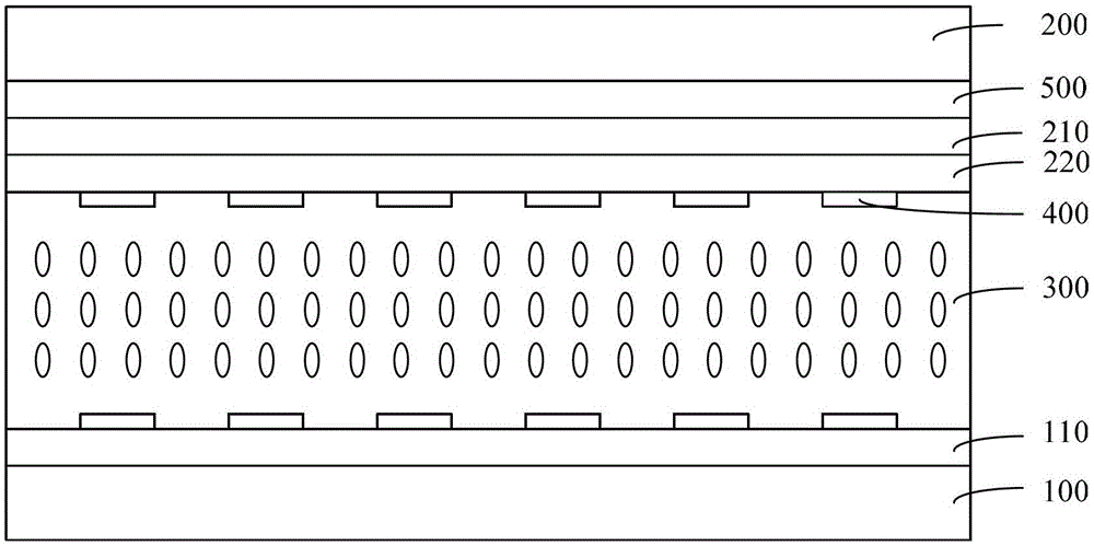
[0044] Specifically, the embodiment of a liquid crystal screen provided in the technical solution of the present invention is as follows Figure 4 to Figure 6 shown. The liquid crystal screen in this embodiment is a liquid crystal touch panel as mentioned above. refer to Figure 4 As shown, in the technical solution of this embodiment, the upper-line polarizer 220 is moved to the outermost surface of the liquid crystal touch panel, and an upper λ / 4 wave plate 204 is added between the upper transparent substrate 200 and the upper-line polarizer 220 A lower λ / 4 wave plate 104 and a lower line polarizer 110 are added outside the lower transparent substrate 100 . That is, on the upper surface of the liquid crystal layer, starting from the outermost layer, there are an upper linear polarizer 220 and an upper λ / 4 wave plate 204 in sequence. That is, on the lower surface of the liquid crystal layer, starting from the outermost layer, there are an upper linear polarizer 110 and a l...
Embodiment 2
[0051] An embodiment of the present invention is specifically as Figure 7 to Figure 10 shown. refer to Figure 7 As shown, in the technical solution of this embodiment, the upper λ / 2 wave plate 215 located between the upper line polarizer 220 and the upper λ / 4 wave plate 204 is added on the basis of the first embodiment, and the lower line polarizer The lower λ / 2 wave plate 115 between the plate 110 and the lower λ / 4 wave plate 104. That is, on the upper surface of the liquid crystal layer, starting from the outermost layer, there are an upper linear polarizer 220 , an upper λ / 2 wave plate 215 and an upper λ / 4 wave plate 204 in sequence. That is, on the lower surface of the liquid crystal layer, from the outside to the inside, there are an upper linear polarizer 110 , a lower λ / 2 wave plate 115 and a lower λ / 4 wave plate 104 .
[0052] In this embodiment, the linear polarizer is marked as PL, the transmission axis direction of the linear polarizer is marked as p, the λ / 4 w...
Embodiment 3
[0063] An embodiment of the present invention is specifically as Figure 13 to Figure 14 As shown, on the basis of the second embodiment, an additional λ / 2 wave plate 225 is added between the upper line polarizer 220 and the λ / 4 wave plate 204, and an additional piece of λ / 2 wave plate 225 is added between the lower line polarizer 110 and the lower λ / 4 wave plate. An additional λ / 2 wave plate 125 is added between the wave plates 104 . That is, on the upper surface of the liquid crystal layer, starting from the outermost layer, there are an upper linear polarizer 220 , λ / 2 wave plates 215 and 225 , and a λ / 4 wave plate 204 . That is, on the lower surface of the liquid crystal layer, from the outside to the inside, there are an upper linear polarizer 110 , a λ / 2 wave plate 115 and 125 , and a λ / 4 wave plate 104 . The newly added λ / 2 can increase the wavelength of new circularly polarized light, so that the wavelength band of the light wave passing through the liquid crystal scr...
PUM
 Abstract
Description
Claims
Application Information