
Touch panel having improved visibility and method of manufacturing the same

一种触控面板、制造方法的技术,应用在绝缘板上的电路布置、支撑结构上的电路布置、数据处理的输入/输出过程等方向

Active Publication Date: 2013-09-11
SAMSUNG ELECTRONICS CO LTD
View PDF5 Cites 7 Cited by
  • Summary
  • Abstract
  • Description
  • Claims
  • Application Information

AI Technical Summary

Problems solved by technology

[0014] Moreover, the conventional touch panel has a defect that the impact transmitted to the side when it is dropped is directly transmitted to the touch panel.

Method used


Image

  • Touch panel having improved visibility and method of manufacturing the same
  • Touch panel having improved visibility and method of manufacturing the same
  • Touch panel having improved visibility and method of manufacturing the same

Examples


no. 1 example

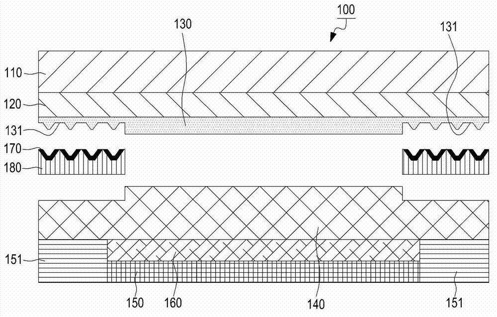
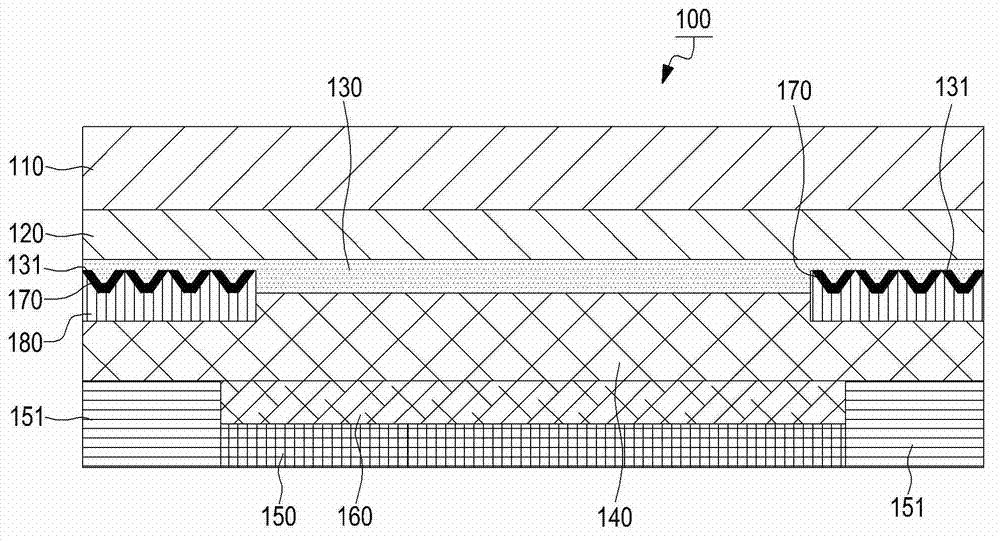
[0037] figure 2 with image 3 It is a diagram showing the composition of the touch panel provided by the present invention.

[0038] Depend on figure 2 with image 3It can be seen that the touch panel 100 includes a window unit 110 with a polymer film layer 120 , a first UV curable resin layer 130 , a second UV curable resin layer 140 , and a display unit 150 with a touch sensor film module 160 . The polymer film layer 120 is pasted on the lower side of the window unit 110 so that the first UV curable resin layer 130 described later can be pasted. The first UV curable resin layer 130 may include the second UV curable resin layer 140 and be pasted on the lower side of the polymer film layer to transmit light. The second UV curable resin layer 140 is disposed on the lower side of the first UV curable resin layer 130 to receive light passing through the first UV curable resin layer 130 and prevent refraction and reflection of the received light. . The touch sensor thin fi...

no. 2 example

[0071] Image 6 with Figure 7 is a diagram showing the composition of a visibility-improved touch panel according to a second embodiment of the present invention.

[0072] refer to Image 6 with Figure 7 The composition of touch panel 200 for improving visibility will be described. The touch panel 200 includes a window unit 210 with a polymer film layer 220 and a display unit 250 with a first UV curable resin layer 230 , a second UV curable resin layer 240 and a touch sensor film module 260 . The polymer film layer 220 is pasted on the lower side of the window unit 210 described later so that the first UV curable resin layer 230 can be pasted. The first UV curable resin layer 230 is provided with a second UV curable resin layer 240 to be described later, and is attached to the lower side of the polymer film layer 220 in order to transmit light. The second UV curable resin layer 240 receives light passing through the first UV curable resin layer 230 , and is pasted on th...


PUM


Abstract

A touch panel having improved visibility is provided. The touch panel includes a window part having a polymer film layer, a first ultraviolet (UV) curable resin layer attached to a bottom surface of the window part, a second ultraviolet (UV) curable resin layer attached to a bottom surface of first ultraviolet (UV) curable resin layer and used for preventing light refraction and reflection, and a display part including a touch sensor film module attached to a bottom surface of the second ultraviolet (UV) curable resin layer.

Description

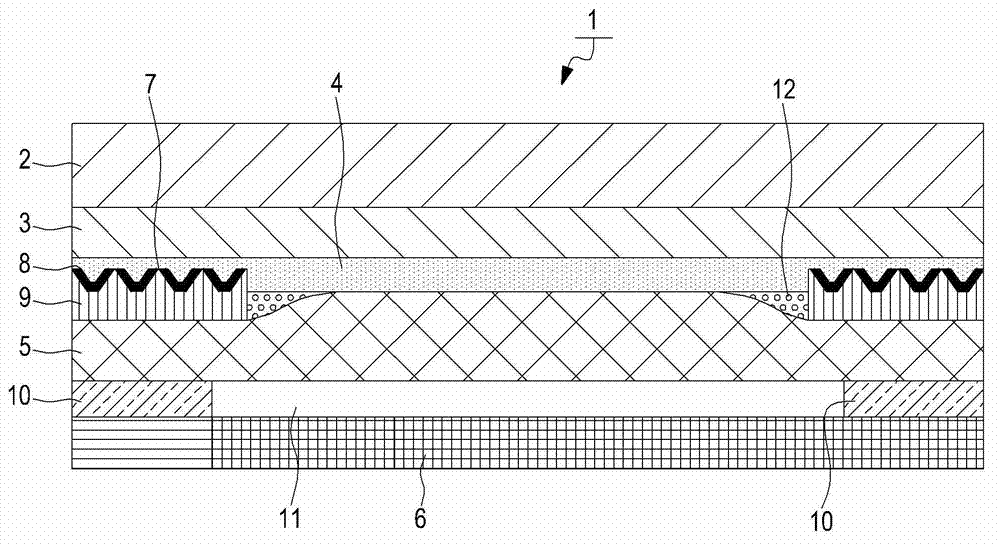
technical field [0001] The present invention relates to a touch panel, and more particularly, to a touch panel having improved visibility by providing a UV curable resin layer capable of preventing refraction and reflection of light, and a manufacturing method thereof. Background technique [0002] Recently, with the rapid development of multimedia technology and display technology, the visibility of portable communication devices has been improved, whereby portable communication terminals often use touch panels. [0003] For a touch panel using a resistive touch sensor, two sensors are required to provide touch position information, so a film needs to be pasted on the display window of a portable communication device. In the control panel, the touch position information is given by sensing the position where the charge changes. [0004] Here, the capacitive touch panel is further described as follows. [0005] Such as figure 1 As shown, the capacitive touch panel 1 inclu...

Claims


Application Information

Patent Timeline
Patent Type & Authority Applications(China)
IPC IPC(8): G06F3/044G06F3/041
CPCG06F3/0412Y10T156/10H05K7/06
Inventor 金明坤金钟禹宋铉明李德镛
Owner SAMSUNG ELECTRONICS CO LTD
Learn More