Manufacturing method of actuating shaft for washing machine

A manufacturing method and drive shaft technology, applied in the field of washing machines, can solve the problems of multiple processing steps and high strength, and achieve the effects of simple manufacturing process, increased strength, and improved production efficiency

Inactive Publication Date: 2005-01-19
LG ELECTRONICS (TIANJIN) APPLIANCES CO LTD
View PDF0 Cites 2 Cited by
  • Summary
  • Abstract
  • Description
  • Claims
  • Application Information

AI Technical Summary

Problems solved by technology

[0014] However, there is an existing drive shaft manufacturing method. First, the first drive shaft 4 and the second drive shaft 5 that constitute the drive shaft S are manufactured separately, and then the first drive shaft 4 is pressed into the second drive shaft 5, and the molded The overall structure is used for secondary processing such as hobbing and grinding
[0015] Therefore, there are many processing steps in the existing drive shaft manufacturing method. In addition, the drive shaft is formed by combining two parts, and its strength is not as high as that of the overall shape.

Method used


Image

  • Manufacturing method of actuating shaft for washing machine
  • Manufacturing method of actuating shaft for washing machine
  • Manufacturing method of actuating shaft for washing machine

Examples


Embodiment Construction

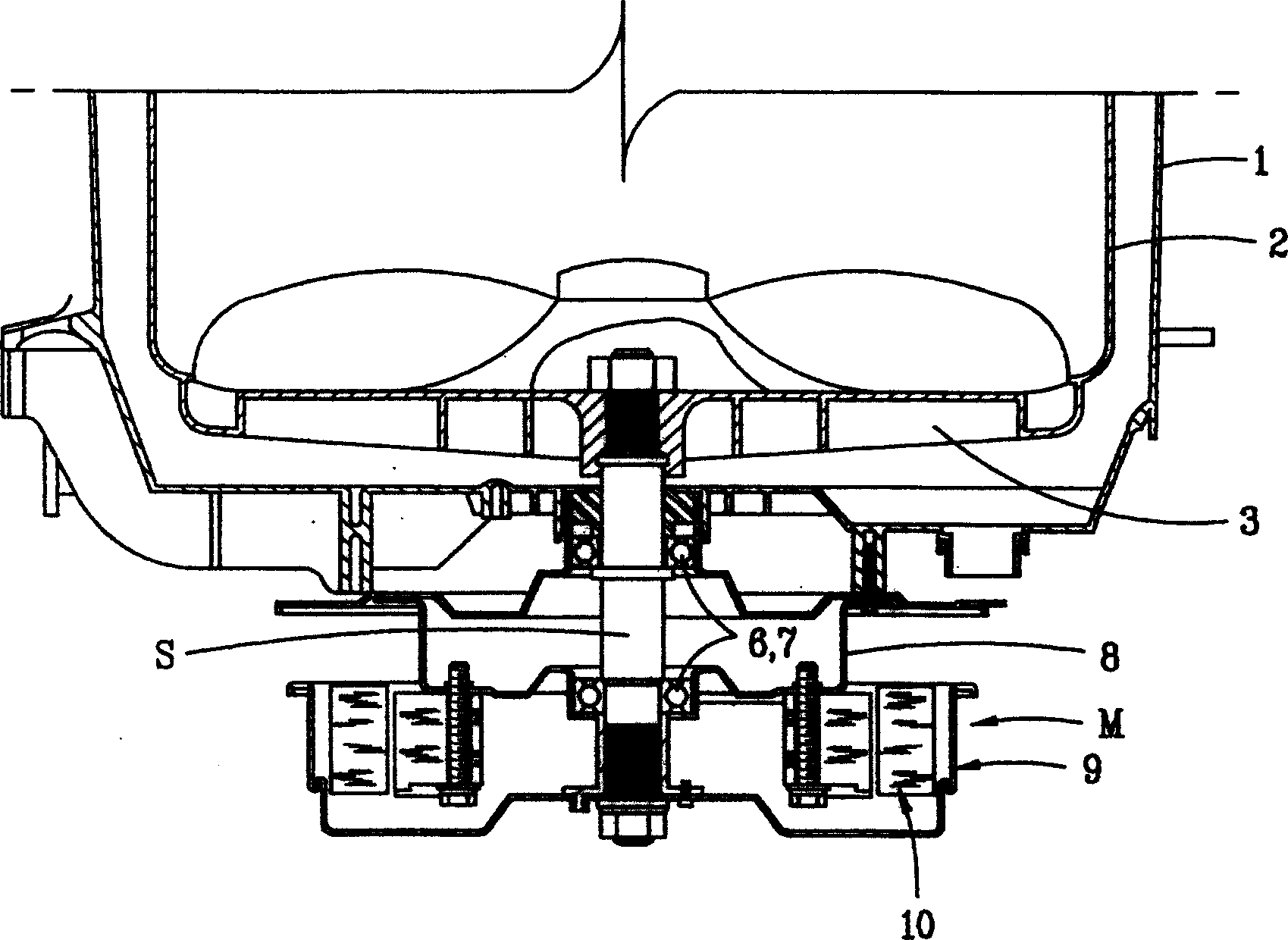
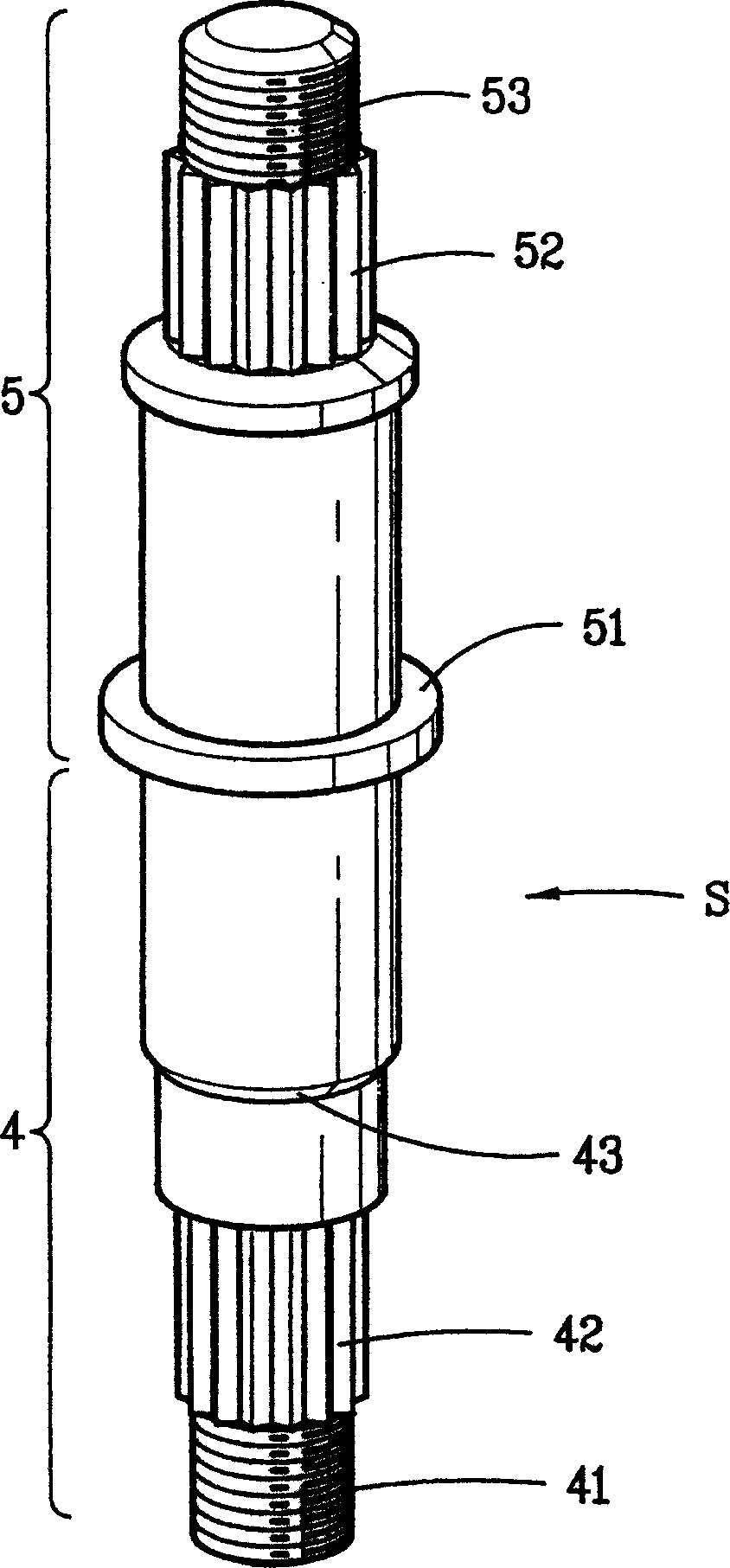
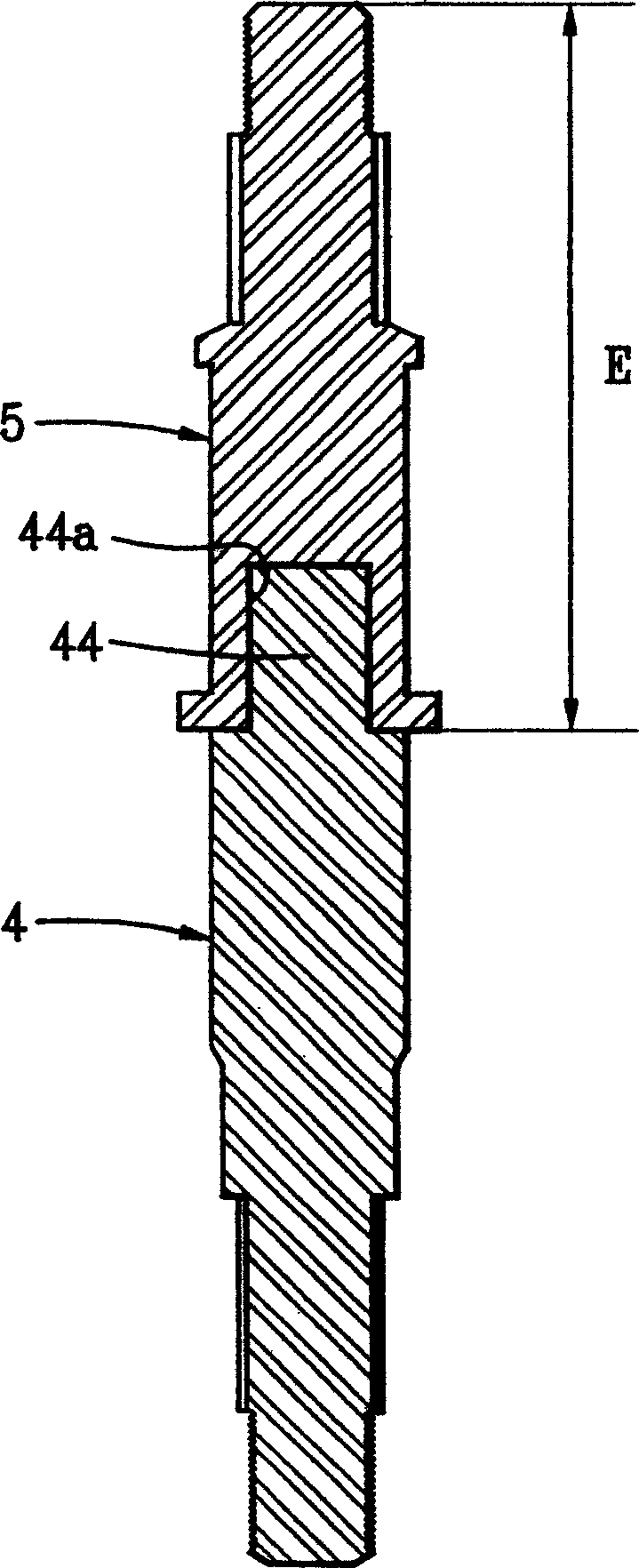
[0029] Refer to the attached Figure 5 Embodiments of the present invention are described in more detail:

[0030] The present invention comprises: a cylinder-shaped water storage bucket 1 for containing washing water; a washing bucket 2 rotating in the water storage bucket 1; a motor M for driving the washing bucket 2; a drive for transmitting the driving force of the motor M to the washing bucket 2 Axis S. The manufacturing method of the drive shaft is carried out according to the following procedures: Cutting process: the drive shaft cuts the stainless steel plate according to the requirements of processing into a cylindrical shape; welding process: welds the joint part of the stainless steel plate after cutting, and welds it into a cylindrical tubular structure; Cutting process: cutting the outer surface of the cylindrical tube into a specified shape; hobbing process: after completing the above cutting process, hobbing is performed on the specified position to form a gear...


PUM


Abstract

The invention provides a preparing method for a driving shaft of a washing machine. The preparing process is as follows: 1) cutting: cutting a stainless steel plate according to the cylinder processing request; 2) welding: welding the joint to obtain a cylinder-shape pipe structure; 3) shaping: shaping the outer surface of the cylinder-shape pipe according to the defined shape; 4) hobbing: having a hobbing process on the defined position and forming a gear; 5) grinding: grinding the tooth surface of the gear. The invention improves the driving shaft preparing method and improves the production efficiency and the strength of the driving shaft.

Description

technical field [0001] The invention relates to a washing machine, in particular to a method for manufacturing a drive shaft for the washing machine. Background technique [0002] A general washing machine includes: a cylindrical water storage bucket filled with washing water; a washing bucket rotating in the water storage bucket; a motor driving the washing bucket; and a drive shaft that transmits the driving force of the motor to the washing bucket. The washing tub is driven by a motor for washing and dehydration. [0003] figure 1 It is a sectional view of the structure of the transmission part of the existing fully automatic washing machine, and the structure of the existing washing machine will be described with reference to this figure. [0004] It can be seen from the figure that the existing washing machine includes: a water storage tub 1 and a washing tub 2 arranged inside it; Hub 3; a pair of bearings 6, 7 and a bearing sleeve 8 supporting the drive shaft; a mot...

Claims


Application Information

Patent Timeline
Patent Type & Authority Applications(China)
IPC IPC(8): B23P17/00D06F37/00
Inventor 孔晟洛
Owner LG ELECTRONICS (TIANJIN) APPLIANCES CO LTD
Why Eureka
Try Eureka