

Injection molding machine
A technology for injection molding machines and cylindrical parts, which is applied in the field of injection molding machines, can solve problems such as energy waste, and achieve the effect of reducing energy consumption
- Summary
- Abstract
- Description
- Claims
- Application Information
AI Technical Summary
Problems solved by technology
Method used
Image

Examples
Embodiment Construction
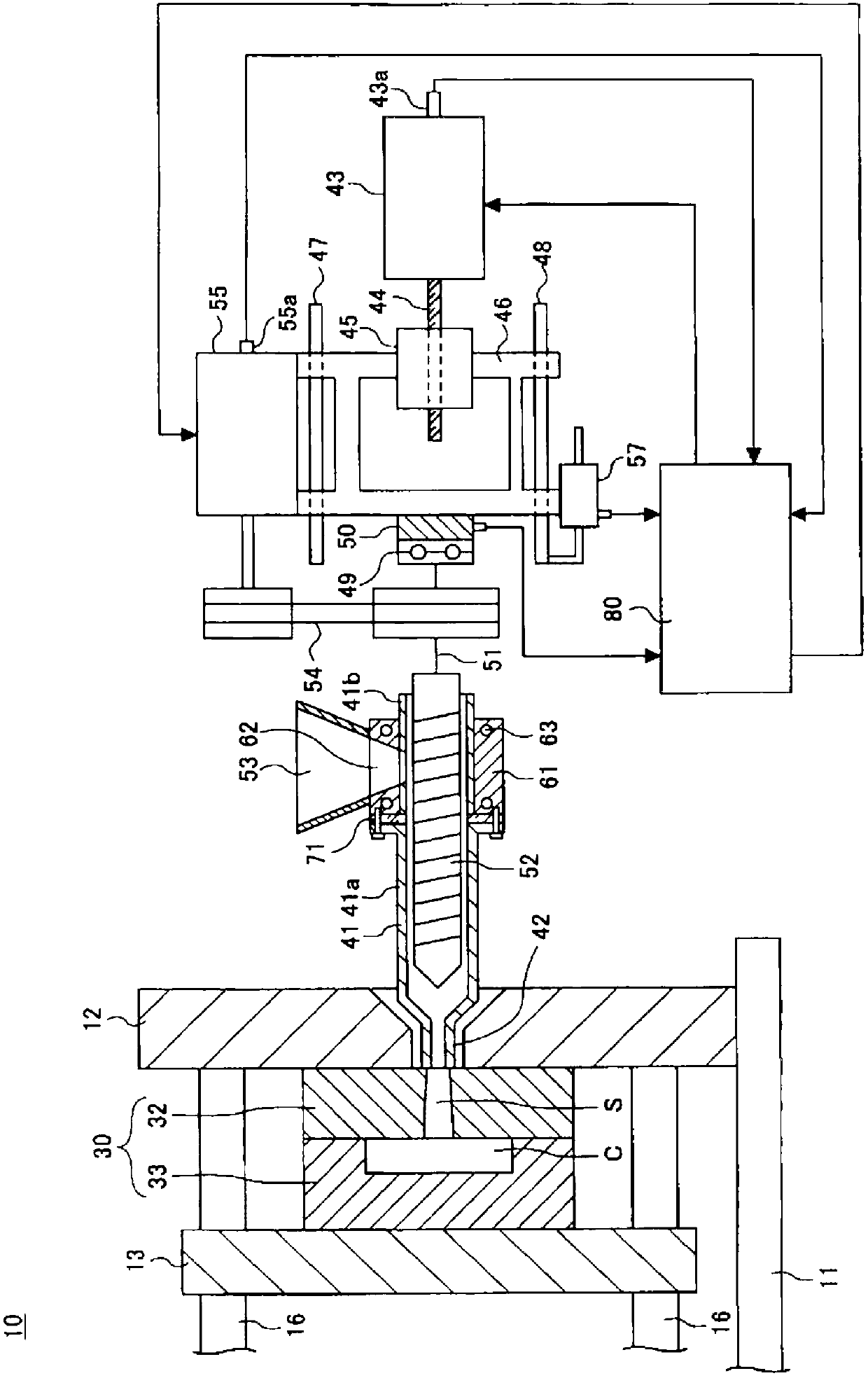
[0032] Hereinafter, modes for carrying out the present invention will be described with reference to the drawings. In each of the drawings, the same or corresponding components are assigned the same or corresponding symbols and descriptions thereof will be omitted. In addition, the direction in which the injection device ejects the resin is referred to as the front, and the direction opposite to the ejection direction is referred to as the rear.
[0033] figure 1 It is a figure which shows the outline of the injection molding machine which concerns on one Embodiment of this invention. figure 1 Indicates the status of mold clamping.
[0034] The injection molding machine 10 includes a frame 11 , a fixed platen 12 fixed on the frame 11 , and a plurality of (for example four) connecting rods 16 extending from the fixed platen 12 . In addition, the injection molding machine 10 further includes a movable platen 13 disposed opposite to the fixed platen 12 and configured to be mova...
PUM
 Abstract
Description
Claims
Application Information