Prosthesis and orthosis

Pending Publication Date: 2020-11-19
MOOG CONTROLS +1
View PDF0 Cites 0 Cited by
  • Summary
  • Abstract
  • Description
  • Claims
  • Application Information

AI Technical Summary

Benefits of technology

[0027]Some or all of the passages may devoid of bends having a radius of curvature of less than half of the passage width or diameter. Preferably the bends have a radius of curvature of less than a third of the passage width or diameter and preferably less than a quarter of the passage width or diameter. By manufacturing the housing using an additive manufacturing methods the shape of the internal passages can be optimised to remove sharp corners and reduce the amount of drag experienced by the hydraulic fluid as it passes through the

Problems solved by technology

Such prostheses require large batteries and frequent recharging.
They also tend to be noisy.
As such there are various problems with known ankle pro

Method used


Image

  • Prosthesis and orthosis
  • Prosthesis and orthosis
  • Prosthesis and orthosis

Examples


Example

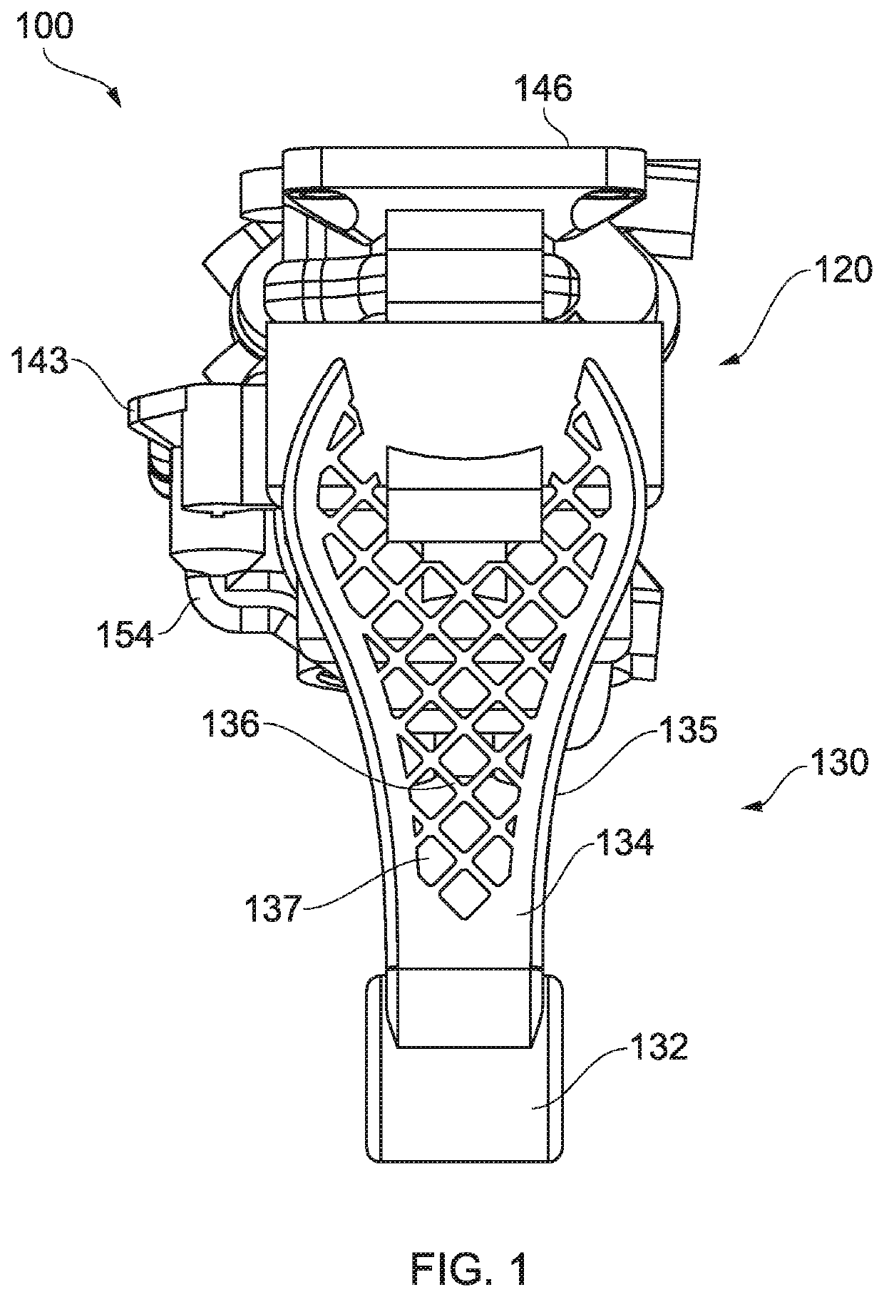
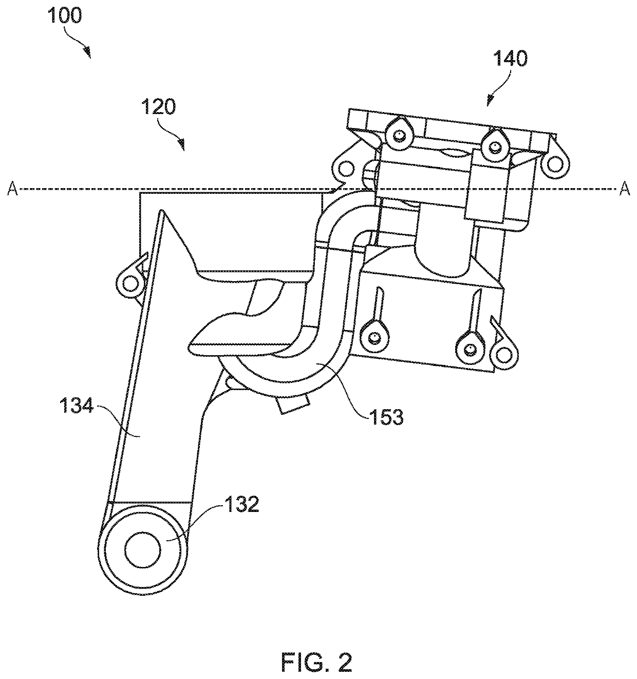
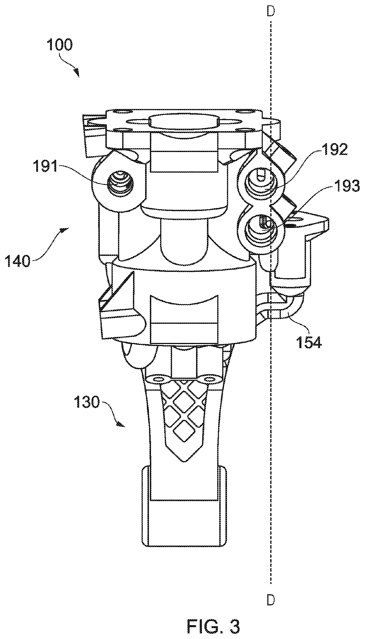
[0058]The first embodiment ankle prosthesis housing 100 comprises three main sections: a piston and cylinder assembly (PACA) section 120, an ankle flexion pivot interface section 130, and an accessory interface section 140.

[0059]The PACA section 120 comprises an outer wall 122 which defines a first, lower cylinder and a second upper cylinder. The first, lower cylinder has a diameter less than the second, upper cylinder and is configured to receive a piston and piston rod.

[0060]The first, lower cylinder comprises a cylindrical wall 122 and a circular base portion 121. An aperture 125 is formed in the base 121 of the first, lower cylinder. The aperture 125 is configured to receive a piston rod which extends from a piston slidably mounted in the first, lower cylinder. A first port 126 is formed in the base 121 of the first, lower cylinder. A second port 127 is formed in an upper portion of the first, lower cylinder.

[0061]The second, upper cylinder is configured to receive a cap which c...


PUM


Abstract

A prosthesis comprises a housing (100); a piston (221) and piston rod (222) housed within a cylinder of the housing (100); and a pump (244) mounted on and partially within the housing (100). The housing (100) is a unitary piece and comprises a plurality of passages (151, 152, 153, 154) connecting the cylinder to the part of the housing (100) where the pump (244) is mounted.

Description

TECHNICAL FIELD[0001]The present invention relates to a prosthesis and orthosis. In particular, the present invention relates to lower limb (ankle or knee) prosthesis and orthosis and a housing for a lower limb prosthesis and orthosis.BACKGROUND TO THE INVENTION AND PRIOR ART[0002]Lower limb prostheses are used to restore an amputee's ability to walk, by supporting the weight of an amputee, for example during a stance phase of walking or running, or when standing.[0003]One type of lower limb prosthesis is referred to as an ankle prosthesis, since such a prosthesis corresponds to, and may be designed to mimic, the function of a human ankle.[0004]There have been various developments in lower limb prostheses, including use of powered systems and active response systems as elaborated in relation to known systems described below.[0005]Known lower limb prostheses include those with adaptive control systems for controlling knee flexion or ankle flexion during both stance and swing phases o...

Claims


Application Information

Patent Timeline
IPC IPC(8): A61F2/66A61F2/50A61F2/64A61F5/01
CPCA61F2/64A61F5/0102A61F2002/745A61F2/5044A61F2002/6614A61F2002/748A61F2/6607A61F2/74A61F2/748A61F2/50A61F5/01A61F2002/5006A61F2/741
Inventor BHATTI, JAWAADZAHEDI, MIR SAEEDMOSER, DAVIDBROOKS, LANDUKE, CHRISTOPHER
Owner MOOG CONTROLS
Why Eureka
Try Eureka