
Turbine housing and method of improving efficiency of a radial/mixed flow turbine

Active Publication Date: 2020-06-04
NANYANG TECH UNIV
View PDF0 Cites 2 Cited by
  • Summary
  • Abstract
  • Description
  • Claims
  • Application Information

AI Technical Summary

Benefits of technology

The patent text describes a turbine housing for a radial / mixed flow turbine that reduces energy losses due to tip leakage, flow separation, and vortices. The turbine housing is not limited to turbocharging applications and can be used for all radial / mixed flow turbines to improve efficiency. The method described involves improving the efficiency of the turbine by using a shroud that partially enshrouds the rotor and has a clearance between the blade tips and the shrug. This results in a more efficient fluid flow through the turbine.

Problems solved by technology

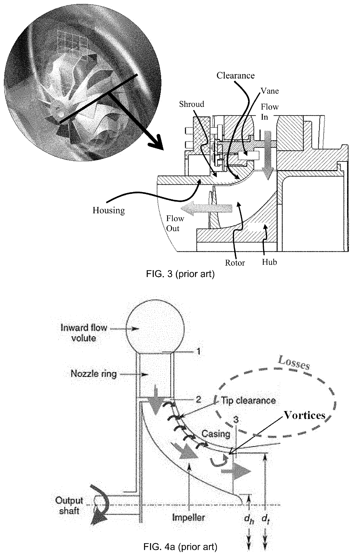
However not all losses can be addressed with conventional housing design, and one of it is the tip leakage loss in the turbine. FIG. 3 shows a meridional view of a turbine wheel in which the flow direction can be seen.
Due to the clearance, some of the high pressure flow will escape into the clearance, without imparting momentum onto the wheel, thus being a source of energy loss in the turbine.
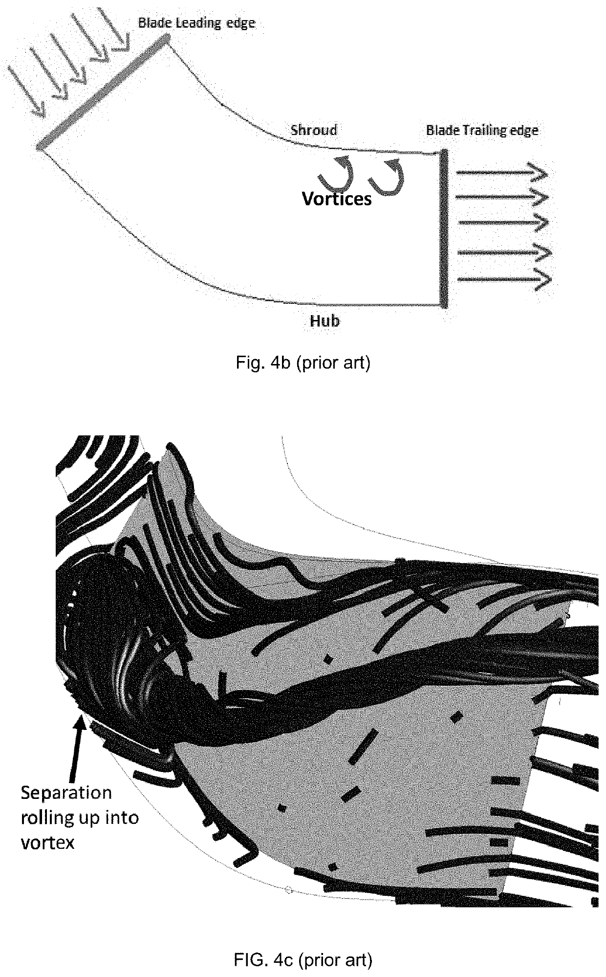
The tip clearance leakage, apart from not imparting momentum, also mixes with the main flow downstream and creates vortices as shown in FIGS. 4a and 4b, which further increases losses in the turbine wheel.
Another source of loss can arise from flow separations within the turbine wheel.
This can come from an unfavourable incidence angle, which leads to flow separation over the turbine wheel blade, which can then roll up into a vortex and increase losses in the turbine wheel.

Method used


Image

  • Turbine housing and method of improving efficiency of a radial/mixed flow turbine
  • Turbine housing and method of improving efficiency of a radial/mixed flow turbine
  • Turbine housing and method of improving efficiency of a radial/mixed flow turbine

Examples


Embodiment Construction

[0076]Exemplary embodiments of a turbine housing 100 and method 200 of improving efficiency of a radial / mixed flow turbine 300 will be described below with reference to FIGS. 5 to 33 in which the same reference numerals are used to denote the same or similar parts.

[0077]As shown in FIGS. 5 to 14, in general, the turbine housing 100 comprises a shroud 10 configured to at least partially enshroud a rotor 90 of a radial / mixed flow turbine 300. The rotor 90 comprises a plurality of blades 80 disposed about a hub 70 and rotates about a rotational axis R of the turbine 300. A clearance 20 is provided between the shroud 10 and blade tips 82 of the plurality of blades 80. The shroud 10 and the hub 70 define a main passage 66 of fluid flow in the turbine 300 in which a main flow 60 of fluid passes. At least one injection opening 12 is provided in the shroud 10. The at least one injection opening 11 is configured to allow injection of a secondary flow 50 of fluid into at least the clearance 2...


PUM


Abstract

A turbine housing for a radial / mixed flow turbine, the turbine having a rotor comprising a plurality of blades disposed about a hub, the turbine housing comprising: a shroud configured to at least partially enshroud the rotor wherein a clearance is provided between the shroud and blade tips of the plurality of blades, the shroud and the hub defining a main passage of fluid flow in the turbine; and at least one injection opening provided in the shroud, the at least one injection opening configured to allow injection of a secondary flow of fluid into at least the clearance between the shroud and the blade tips.

Description

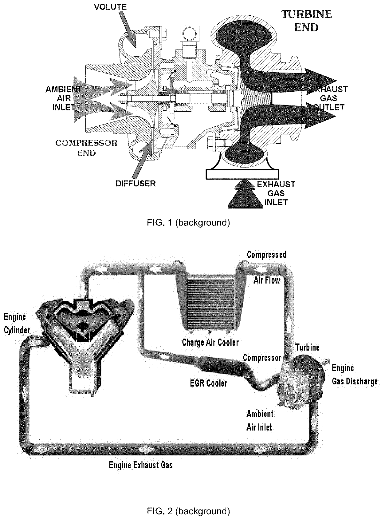
FIELD OF INVENTION[0001]This invention relates to a turbine housing and method of improving efficiency of a radial / mixed flow turbine.BACKGROUND[0002]Fuel in an internal combustion engine requires a finite mass of air in order to achieve and sustain combustion which uses oxygen in the air. The relation between the amount of fuel and air in an engine is called the air-to-fuel ratio. In an internal combustion engine, the air-to-fuel ratio is fixed and it is a design parameter of the engine itself. In addition to this, engine power is directly proportional to the amount of fuel being burnt. By delivering more air into an engine using a turbocharger, which is one of many applications of a radial / mixed flow turbine, more fuel can be burned. This enables a turbocharged engine to produce more power and torque compared to an equivalent naturally aspirated engine.[0003]A typical turbocharger as shown in FIG. 1 comprises a single-stage radial-flow (“centrifugal”) compressor driven by a single...

Claims


Application Information

Patent Timeline
IPC IPC(8): F01D11/10F02B37/10F02C6/08
CPCF02C6/08F05D2220/40F01D11/10F02B37/10F02B37/164F02B37/18F02B37/20F01D17/165Y02T10/12
Inventor ROMAGNOLI, ALESSANDRORAJOO, SRITHARMARTINEZ-BOTAS MATEO, RICARDO FERNANDOLIU, HAO
Owner NANYANG TECH UNIV
Learn More