Carriage and recording apparatus

a recording apparatus and carriage technology, applied in the direction of printing, inking apparatus, other printing apparatus, etc., can solve the problems of fine turbulence, variation in the landing position of ink,

Active Publication Date: 2020-02-04
SEIKO EPSON CORP
View PDF7 Cites 0 Cited by
  • Summary
  • Abstract
  • Description
  • Claims
  • Application Information

AI Technical Summary

Benefits of technology

[0010]The plasma actuators apply the air current further to the first air current flowing along the nozzle surface. The first air current affects the turbulence in the second air current traveling in the travel direction of the ink droplets, and prevents the turbulence in the second air current occurring in the peripheries of the ink droplets from stagnating. Accordingly, the ink droplets traveling can be prevented from being affected by the turbulence in the second air current. As a result, the carriage can prevent the ink droplets landing on the recording medium from forming a ripple-like pattern.Application Example 2
[0017]According to Application Example 4, the carriage includes the main body unit configured to support the head and the plasma actuators. The air current surface is a surface on which a gas flowing along the nozzle surface flows in the main body. At least either the plurality of concave portions or the plurality of convex portions are disposed on the air current surface. Some of the air current flowing along the air current surface flows along the concave portions or the convex portions, and also some of the air current travels straight. In this case, the air current flowing along the concave portions or the convex portions and the air current traveling straight interfere each other and generate fine turbulence. Fluid body resistance in the air current surface can be reduced by this turbulence. As a result, the first air current can flow efficiently.Application Example 5

Problems solved by technology

However, when there is a high ink droplet discharge rate to increase a drawing speed, vortices generated in a nozzle arrangement direction result in a variation in the landing positions of the ink droplets.
In this case, the air current flowing along the concave portions or the convex portions and the air current traveling straight interfere each other and generate fine turbulence.

Method used


Image

  • Carriage and recording apparatus
  • Carriage and recording apparatus
  • Carriage and recording apparatus

Examples


first exemplary embodiment

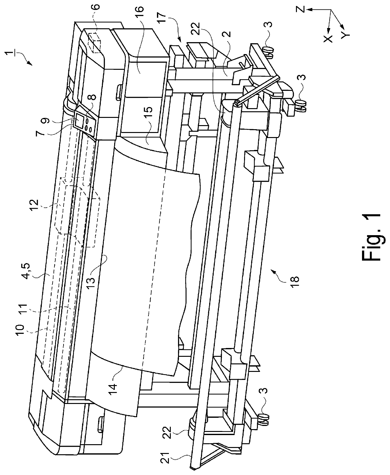
[0044]A first exemplary embodiment will describe an example of a recording apparatus with reference to the drawings. The recording apparatus according to the first exemplary embodiment will be described with reference to FIGS. 1 to 16. FIG. 1 is an overall perspective view illustrating a structure of the recording apparatus. As illustrated in FIG. 1, a recording apparatus 1 is a roll-to-roll type large-format ink jet printer configured to handle a recording medium comparatively large. The recording apparatus 1 has a shape longer in one direction along the ground. A lengthwise direction of the recording apparatus 1 corresponds to an X-axis direction, and a left side in FIG. 1 corresponds to a +X-axis direction. A direction orthogonal to the X-axis direction along the ground corresponds to a Y-axis direction. A direction of gravitational acceleration corresponds to a −Z-axis direction.

[0045]The recording apparatus 1 includes legs 2. Wheels 3 are provided on the −Z-axis direction sides...

modified example 1

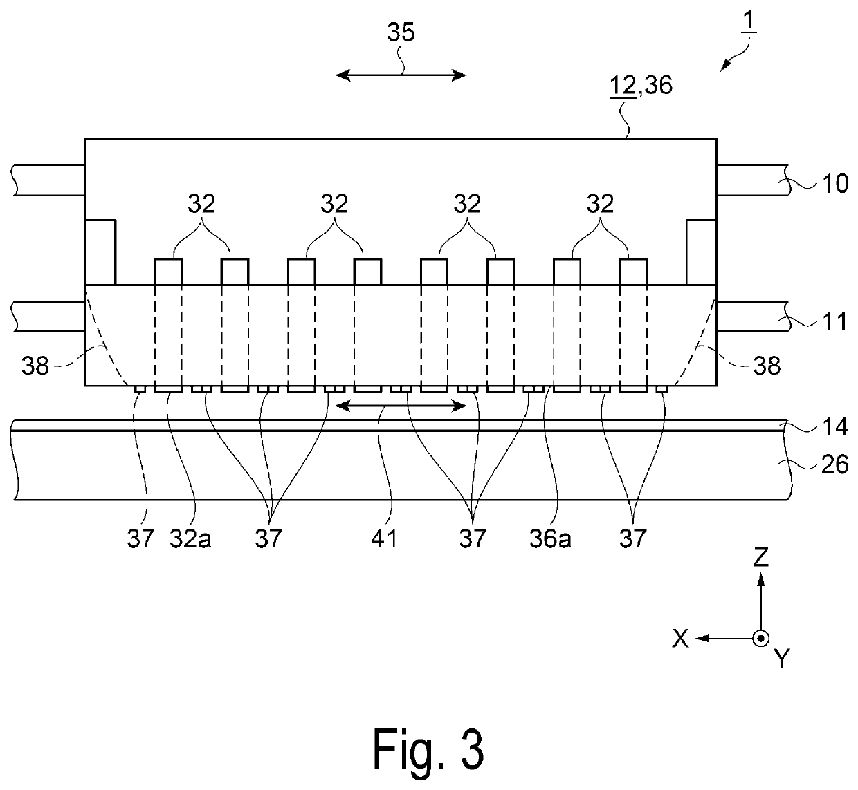
[0112]In the first exemplary embodiment, the nozzle row 44 is located within the range where the plasma actuators 37 apply the air current 41a in the second direction 42. When the ink droplets 55 landing on the recording medium 14 and present in a place facing a portion at the end of the nozzle row 44 do not form a ripple-like pattern, the portion at the end of the nozzle row 44 may not be located within the range where the plasma actuators 37 apply the air current 41a in the second direction 42. In other words, the plasma actuators 37 may not be provided in a place where a ripple-like pattern is not formed. Since the length in the second direction 42 of each of the plasma actuators 37 is reduced, the weight of the carriage 12 is reduced.

modified example 2

[0113]In the first exemplary embodiment, the carriage 12 moves back and forth in the first direction 35. The plasma actuators 37 are disposed to sandwich each head unit 32 in the first direction 35. When the direction in which the carriage 12 moves as the ink droplets 55 are ejected from the nozzles 43 is one direction, each of the plasma actuators 37 may be disposed on one side in the first direction 35 of each head unit 32. Then, the plasma actuators 37 may be disposed on the sides of the head units 32 corresponding to the direction in which the head units 32 move as the ink droplets 55 are ejected. In this case, similarly, the plasma actuators 37 are capable of applying the air current 41a along the nozzle surface 32a. Then, since the number of the plasma actuators 37 is reduced, the weight of the carriage 12 is reduced.


PUM


Abstract

Provided is a carriage including a head including a nozzle surface, the nozzle surface including nozzles configured to eject ink droplets, and a plasma actuator configured to apply an air current flowing along the nozzle surface.

Description

BACKGROUND1. Technical Field[0001]The disclosure relates to a carriage and a recording apparatus.2. Related Art[0002]Ink jet-type recording apparatuses are in wide use. In an ink jet-type recording apparatus, ink is ejected from nozzles as ink droplets, and positions where the ink droplets land are controlled. Then, a predetermined pattern is drawn with the ink droplets. There is demand for shortening time taken for printing to improve convenience. Further, the number of ink droplets ejected per unit of time is increased to accelerate drawing.[0003]A plurality of nozzles are provided in a nozzle head, and a plurality of the nozzle heads are provided in a carriage. Then, the carriage moves parallel to a printing medium. Ink droplets are ejected simultaneously from the plurality of nozzles. Then, when the ink droplets travel from the nozzles toward the printing medium, an air current is generated as the ink droplets travel. This air current is turbulence and a form of the current vari...

Claims


Application Information

Patent Timeline
Patent Type & Authority Patents(United States)
IPC IPC(8): B41J2/14
CPCB41J2/1433B41J2/15B41J2202/02B41J2/2132B41J29/377
Inventor YOSHIMURA, AKIHIROKANEKO, KENICHIROSASAKI, TSUNEYUKI
Owner SEIKO EPSON CORP
Why Eureka
Try Eureka