Heat dissipation apparatus

Inactive Publication Date: 2005-06-14
SIMPLO TECH COMPANY
View PDF9 Cites 28 Cited by
  • Summary
  • Abstract
  • Description
  • Claims
  • Application Information

AI Technical Summary

Benefits of technology

[0004]The present invention provides a heat dissipation apparatus which integrates two sets of fans into a single

Problems solved by technology

The serial connection of the fans 2A and 2A′ results in significant r

Method used


Image

  • Heat dissipation apparatus
  • Heat dissipation apparatus
  • Heat dissipation apparatus

Examples


Example

[0015]Reference will now be made in detail to the preferred embodiments of the present invention, examples of which are illustrated in the accompanying drawings. Wherever possible, the same reference numbers are used in the drawings and the description to refer to the same or like parts.

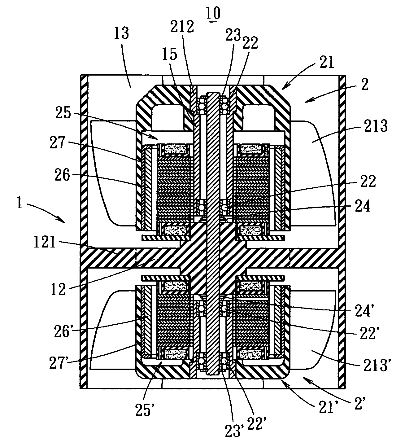
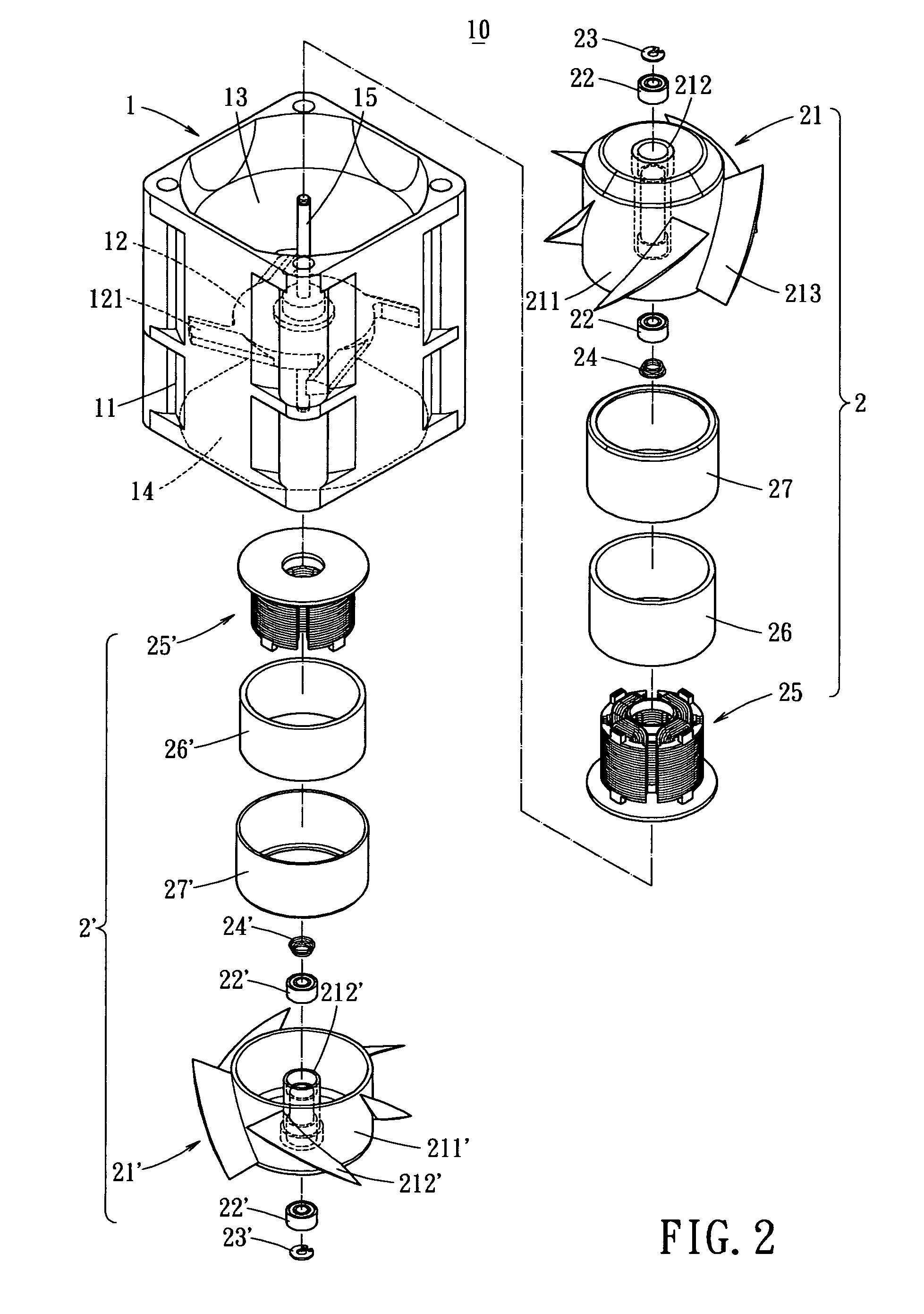
[0016]The present invention provides a heat dissipation apparatus 10 as shown in FIG. 2. The heat dissipation apparatus 10 includes an enclosure or housing 1, in which a lateral fan seat 12 (as shown in FIG. 4) is integrally formed. The fan seat 12 divides an interior space of the enclosure 10 into an upper chamber 13 and a lower chamber 14 to accommodate two sets of fans 2 and 2′ therein, respectively. As shown, the fan seat 12 includes a substantially circular dish and at least one guiding blades 121 (stationary blade) extending radially from a periphery of the body dish. The heat dissipation apparatus 10 further comprises a shaft 15 extending through a center of the fan seat 12 into both the upper...


PUM


Abstract

A heat dissipation apparatus has an enclosure, in which a lateral fan seat is integrally formed with the enclosure. The lateral fan seat divides the interior space of the enclosure into an upper chamber and a lower chamber. An axis is installed across the upper and the lower chambers through a center of the fan seat. A coil set, a magnetic element and a plurality of blades are mounted about the axis in each of the upper and lower chambers. Thereby, two sets of fans are formed in a single enclosure to increase the heat dissipation effect while the assembly convenience is improved.

Description

BACKGROUND OF THE INVENTION[0001]The present invention relates to a heat dissipation apparatus, and more particular, to a heat dissipation apparatus including two sets of fans installed within a single enclosure. Therefore, an enhanced dissipation effect is resulted because the speed and pressure generated by rotation of the fan can be adjusted according to specific requirement, while the assembly convenience is improved.[0002]To enhance overall wind speed and pressure, two heat dissipation fans 2A and 2A′ are typically combined or stacked in series as shown in FIG. 1. Thereby, the damage of the system caused interruption of any of the fans can be avoided. However, to assemble the fans 2A and 2A′ together, fasteners such as screws have to be applied to the frames of the fans 2A and 2A′.[0003]When the fans 2A and 2A′ are secured to each other in series, increase in wind pressure is not significant because the frames of the fans 2A and 2A′ normally include ribs 21A for reinforcing sta...

Claims


Application Information

Patent Timeline
IPC IPC(8): F01P5/02F01P5/04F24H3/02F24H3/06F04D19/00F04D25/06
CPCF04D19/007H05K7/20172F04D25/0613
Inventor SU, SHENG-PINLIU, FENG ZHICHEN, SHIH H.
Owner SIMPLO TECH COMPANY
Why Eureka
Try Eureka