Method for casting rotary axis casts of aerogenerators

A technology of wind power generators and rotating shafts, applied in the direction of casting molding equipment, casting molds, casting mold components, etc., can solve the problems of increasing the production cost of casting products, increasing shrinkage cavities, shrinkage porosity, and slag inclusions, etc., and achieve reduction The effect of production cost, improvement of yield rate, and good slag blocking effect

Active Publication Date: 2010-01-06
RIYUE HEAVY IND
0 Cites 27 Cited by

AI-Extracted Technical Summary

Problems solved by technology

[0003] For such large shaft parts, the slag substances in the molten iron in the casting system of the traditional casting method will inevitably deposit in the casting, which is prone to casting defects, that is, slag inclusions, and also increases shrinkage cavities, The probability of shrinkage porosity will eventually lead to the scrapping of castings and the low yield of castings
In order to reduce the impact of slag inclus...

Abstract

The invention discloses a method for casting rotary axis casts of aerogenerators, which comprises the steps of mould manufacture, the manufacture of sand moulds and moulding by casting. In the step b of the manufacture of sand moulds, a top sprue (1) is used as an inlet of iron liquor, and is alternately communicated with runners; a bottom runner is communicated with an ingate communicated with a cast mould cavity; the runners are designed into a first runner (3), a second runner (4) and a circular runner (5); the ingate is designed into a plurality of radial runners (6) for communicating the circular runner (5) and the cast mould cavity; filtering apparatuses are arranged on the first runner (3) and the second runner (4), and are also arranged between each radial runner (6) and the circular runner (5); and in the step c of moulding by casting, the casting temperature is controlled from 1310 DEG C to 1350DEG C; and finally, a cast (2) is obtained. The method for casting rotary axis cast of aerogenerator has the advantages of good residue blocking effect and low production cost.

Application Domain

Technology Topic

Image

  • Method for casting rotary axis casts of aerogenerators
  • Method for casting rotary axis casts of aerogenerators
  • Method for casting rotary axis casts of aerogenerators

Examples

  • Experimental program(1)

Example Embodiment

[0023] The present invention will be further described below in conjunction with the drawings and specific embodiments.
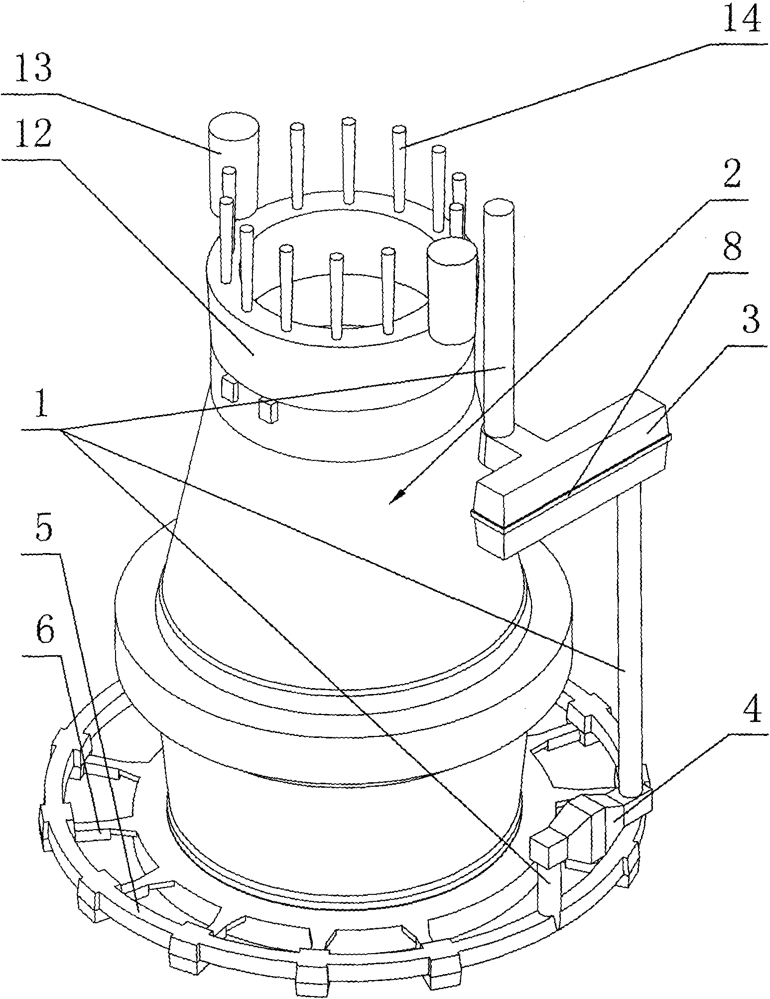
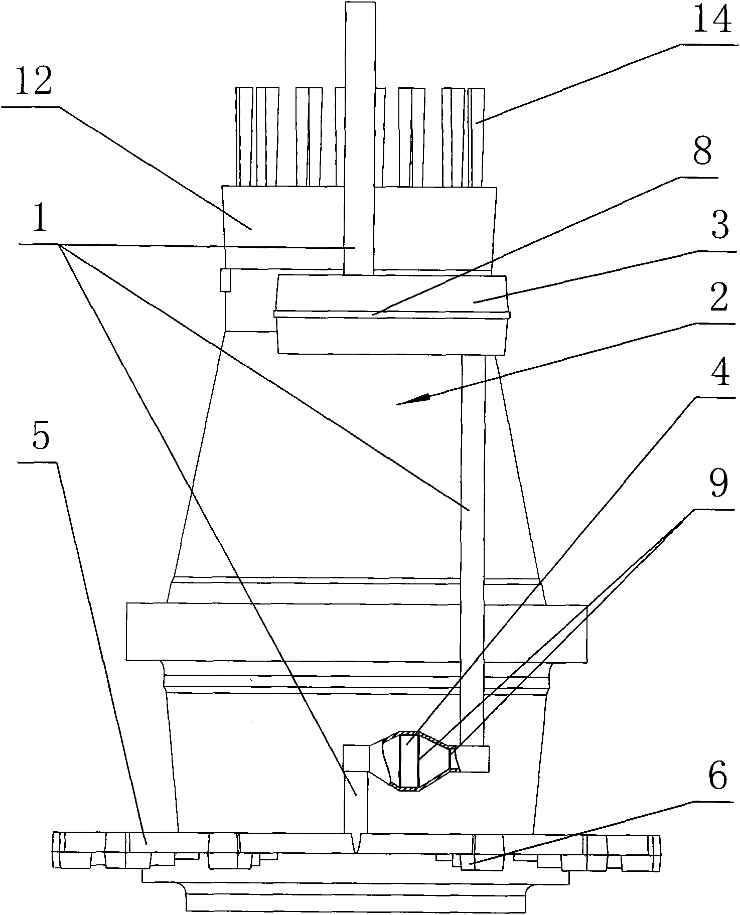
[0024] Such as figure 1 , figure 2 , image 3 , Figure 4 , Figure 5 As shown, the casting method of the wind turbine shaft casting of the present invention includes the following steps: a, mold manufacturing; b, sand mold manufacturing; c, casting molding;
[0025] When the sand mold is manufactured in the step b, the sprue 1 with the highest position is used as the molten iron inlet, the sprue 1 and the runner are alternately connected, and the runner with the lowest position is connected to the inner runner. The channel communicates with the casting cavity.
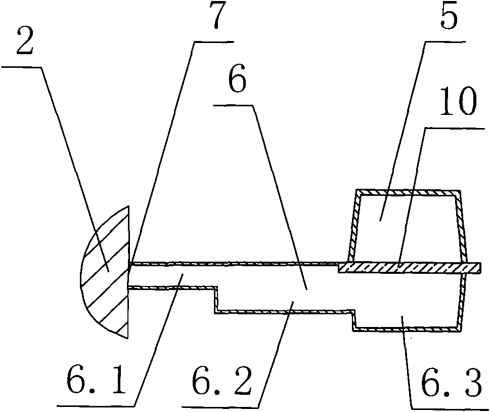
[0026] The runner is designed as the first runner 3 with the highest position, the second runner 4 in the middle, and the ring runner 5 with the lowest position. The inner runners are designed into a plurality of radial runners 6 distributed radially and connected to the annular runner 5 and the casting cavity, and the inner gate 7 of each radial runner 6 is arranged at the lower end of the casting cavity On the circumference.
[0027] A filter device is arranged on the first runner 3, that is, a horizontal first filter brick layer 8 is arranged on the height center line of the first runner 3. The cross section of the first runner 3 is designed into two trapezoids symmetrical about the height center line, and the height center line is the bottom bottom of the two trapezoids.
[0028] A filter device is set on the second runner 4, that is, two layers of vertical filter cloth 9 are arranged in the middle section of the second runner 4, and a layer of vertical filter cloth is arranged at the entrance of the second runner 4 9. The longitudinal section of the second runner 4 is designed as a rectangle in the middle and two trapezoids symmetrical along the rectangle on both sides, and the bottom of each trapezoid is the long side of the rectangle.
[0029] A filter device is arranged between each radial runner 6 and the annular runner 5, that is, a second filter brick layer 10 is arranged between each radial runner 6 and the annular runner 5.
[0030] The cross section of the annular runner 5 is designed as a trapezoid with the bottom of the trapezoid underneath. Each radial runner 6 is designed as an inner section 6.1, a middle section 6.2 and an outer section 6.3, and the outer section 6.3 is set below the annular runner 5. It is connected with the annular runner 5, and the bottom surfaces of the inner section 6.1, the middle section 6.2 and the outer section 6.3 are designed to descend in a stepped shape, and the second filter brick layer 10 is arranged at the junction of the outer section 6.3 and the annular runner 5. The top-view shape of the inner section 6.1 is designed into a bell mouth shape, and the largest cross-sectional area of ​​the inner section 6.1 is located at the inner gate 7.
[0031] A 200mm long body riser 12 is designed on the upper plane of the casting cavity. The blanking riser 13 and a plurality of gas outlet pipes 14 are designed on the main body riser 12, this embodiment uses two blanking risers 13 with a diameter of Φ100mm.
[0032] Place the cold iron 11 at each hot pitch circle of the casting cavity, of which a ring of cold iron 11 is placed under the hot pitch circle at the bottom of the casting cavity, and placed below the hot pitch circle at the middle shoulder of the casting cavity One circle of cold iron 11, two circles of cold iron 11 are arranged at the hot pitch circle on the upper part of the casting cavity.
[0033] When said step c is cast, the chemical composition of the molten iron is: carbon content is 3.74%; silicon content is 1.90%; manganese content is 0.090%; sulfur content is 0.011%; carbon equivalent is 4.37%; The spheroidizing process is carried out before the molten iron is cast, and the spheroidizing grade is level 2. Under the condition of ensuring spheroidization, the residual magnesium content of the molten iron should be controlled within 0.03%~0.05%, the amount of residual rare earth should be controlled within 0.01%~0.03%; the amount of spheroidizing agent should be controlled within the range of 1.3%~1.5% Inside. The casting temperature was 1330°C, the casting time was 45 seconds, and finally casting 2 was obtained.

PUM

no PUM

Description & Claims & Application Information

We can also present the details of the Description, Claims and Application information to help users get a comprehensive understanding of the technical details of the patent, such as background art, summary of invention, brief description of drawings, description of embodiments, and other original content. On the other hand, users can also determine the specific scope of protection of the technology through the list of claims; as well as understand the changes in the life cycle of the technology with the presentation of the patent timeline. Login to view more.

Similar technology patents

Macromonomer based light-curable dental impression material

ActiveUS20190350818A1Reduce shrinkageExcellent tear resistanceImpression capsDental impression compositionsChemistryPhotoinitiator
Owner:DENTSPLY SIRONA INC

Casting technology of planet carrier

InactiveCN108607959AImprove feeding effectReduce shrinkageFoundry mouldsFoundry coresProcess systemsPlanet
Owner:如皋岩达机械工业有限公司

Visual laryngoscope with auxiliary angle adjusting structure

PendingCN112450863AInhibit the growth of bacteriaReduce shrinkageBronchoscopesLaryngoscopesLaryngoscopesBiomedical engineering
Owner:钦州市第一人民医院

Classification and recommendation of technical efficacy words

  • Reduce shrinkage
  • Improve yield

Lithium silicate glass ceramic

ActiveUS20090038344A1High chemical durabilityReduce shrinkageDental implantsOther chemical processesHigh intensityLithium
Owner:IVOCLAR VIVADENT AG

Lithium silicate glass ceramic

ActiveUS20090038508A1High chemical durabilityReduce shrinkageDental implantsImpression capsHigh intensityLithium
Owner:IVOCLAR VIVADENT AG

Lithium ion battery diaphragm and preparation method thereof

Owner:河南惠强新能源材料科技股份有限公司

Filled fiber reinforced thermoplastic composite

InactiveUS20050238864A1Low densityReduce shrinkageSynthetic resin layered productsCeramic layered productsThermoplastic compositesFiber reinforcement
Owner:3M INNOVATIVE PROPERTIES CO

Protected dry composites

InactiveUS20050186305A1Reduce shrinkageReduce migrationAnimal feeding stuffAccessory food factorsBiologyAmino acid
Owner:RGT UNIV OF CALIFORNIA

Krill oil process

Owner:PRONOVA BIOPHARMA NORGE

Method for preparing porous alumina ceramic supporting body with sol as additive

InactiveCN101412620ASolve the cracking problemImprove yieldHoneycombAlumina ceramic
Owner:XI AN JIAOTONG UNIV
Why Eureka
Try Eureka