Aseptic packaging installation with aseptic buffer zones

a technology of aseptic packaging and buffer zones, which is applied in the direction of special packaging, liquid bottling, packaging goods types, etc., can solve the problems of less aseptic air in the packaging zone, not providing for lateral access, and reducing the risk of pollution, so as to reduce the risk of pollution

Inactive Publication Date: 2006-08-24
SERAC GROUP
View PDF10 Cites 28 Cited by
  • Summary
  • Abstract
  • Description
  • Claims
  • Application Information

AI Technical Summary

Benefits of technology

[0006] An object of the invention is to provide an aseptic packaging installation that minimizes the risk of pollution in the packaging zone while enabling action to be taken at various points of the installation.

Problems solved by technology

It has been found that when a technician seeks to act on the line of machines, either for periodic maintenance, or because of a problem that has arisen during the operation of one of the machines, opening a door providing communication between the operator zone and the packaging zone leads to turbulence that runs the risk of causing less-aseptic air to penetrate from the operator zone into the packaging zone, thereby causing the air in the packaging zone to become less aseptic.
Such an installation does not provide for the possibility of lateral access.

Method used


Image

  • Aseptic packaging installation with aseptic buffer zones
  • Aseptic packaging installation with aseptic buffer zones

Examples


Embodiment Construction

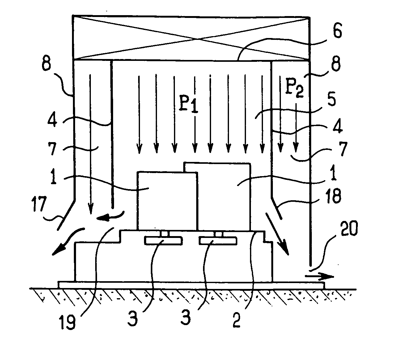
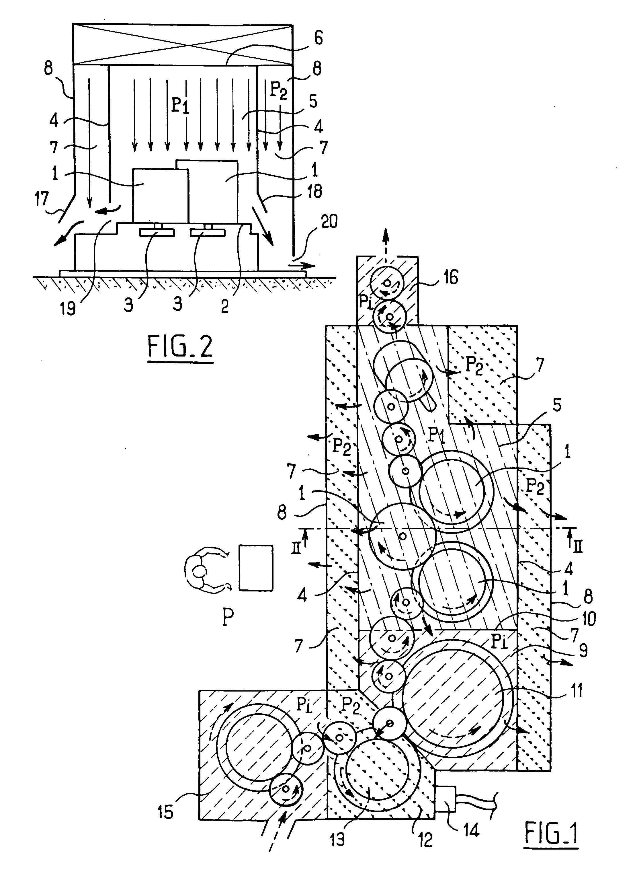
[0013] With reference to the figures, the aseptic packaging installation shown is for packaging a product in receptacles (not shown). In conventional manner, the installation comprises a line of machines 1 such as filler machines, means for heat-sealing capsules, and means for fitting stoppers, all mounted on a bench 2 beneath which there are disposed drive members 3 for driving the machines 1. Walls 4 define a packaging zone 5 subjected to a sterile laminar flow traveling vertically from the ceiling 6 at a rate that is adapted to establish a first pressure P1 in the packaging zone 5 that is higher than the pressure P surrounding the installation. To symbolize the pressure P1, the packaging zone 5 is shaded with fine chain-dotted lines. In order to enable the packaging zone 5 to be pressurized while encouraging a vertical flow of sterile air, the partitions 4 have bottom edges defining a gap 19 that is a few tens of centimeters wide above the bench 2. The first pressure P1 is the re...


PUM

PropertyMeasurementUnit
pressureaaaaaaaaaa
pressureaaaaaaaaaa
pressure P1aaaaaaaaaa

Abstract

The aseptic packaging installation comprises a bench under a ceiling, a line of machines mounted on the bench in a packaging zone subjected to a sterile laminar flow traveling vertically from the ceiling at a rate adapted to establish a first pressure in the packaging zone that is higher than a surrounding pressure, an intervention zone adjacent to the packaging zone, and subjected to a one-way flow of clean air travelling vertically from the ceiling of the intervention zone at a rate that is adapted to establish a second pressure in the intervention zone that is lower than the first pressure but higher than the surrounding pressure.

Description

[0001] The present invention relates to an aseptic packaging installation. BACKGROUND OF THE INVENTION [0002] It is known that in order to ensure long duration conservation of foodstuffs without subjecting them to particular refrigeration conditions, it is necessary for the foodstuff to be conditioned aseptically, i.e. without germs being introduced into the receptacle during the various stages of packaging. In order to ensure that packaging is aseptic, it is known in particular that it is necessary to subject the line of machines used for packaging to sterile conditions that are generally obtained by implementing a laminar flow of filtered air that flows vertically over the line of machines. [0003] For this purpose, existing aseptic packaging installations, such as that described in particular in document FR-A-2 800 710, comprise a cabin that provides a highly aseptic packaging zone around the line of machines, at least one side of the packaging zone being adjacent to an operator z...

Claims


Application Information

Patent Timeline
Patent Type & Authority Applications(United States)
IPC IPC(8): B65B65/08
CPCB65B55/025B67C2003/2688
Inventor RAYNAUD, DELPHINE
Owner SERAC GROUP
Why Eureka
Try Eureka