Device and method for hot embossing of a polymer layer

Active Publication Date: 2011-02-24
EV GRP E THALLNER GMBH
View PDF15 Cites 0 Cited by
  • Summary
  • Abstract
  • Description
  • Claims
  • Application Information

AI Technical Summary

Benefits of technology

[0006]The object of the invention is therefore to devise a device and a method for hot embossing o

Problems solved by technology

Different approaches such as shortening of thermal cycles, for example by use of polymers with low glass transition temperature, or the

Method used


Image

  • Device and method for hot embossing of a polymer layer
  • Device and method for hot embossing of a polymer layer
  • Device and method for hot embossing of a polymer layer

Examples


Example

[0023]The same components and components with the same function are identified with the same reference numbers in the figures.

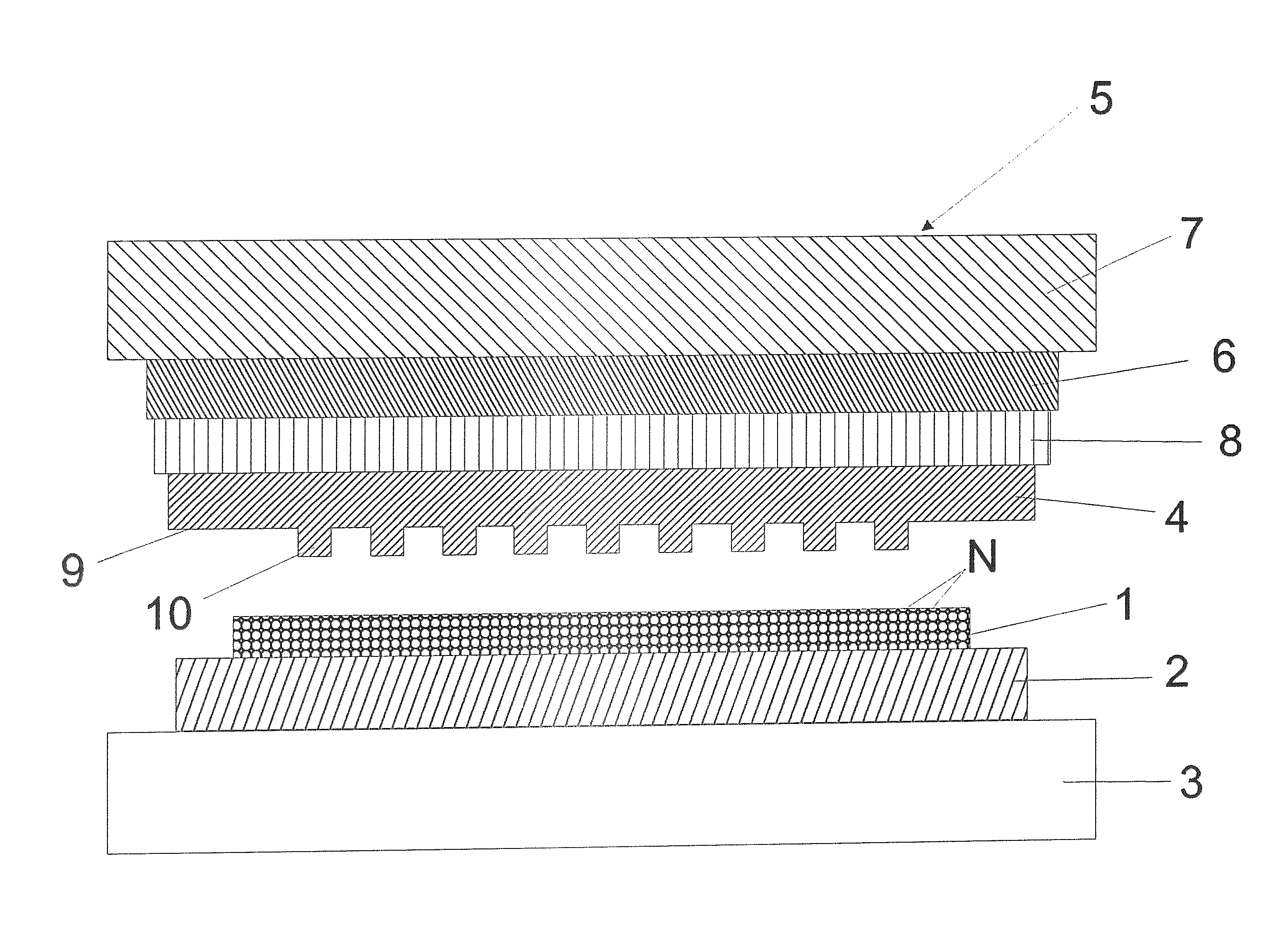
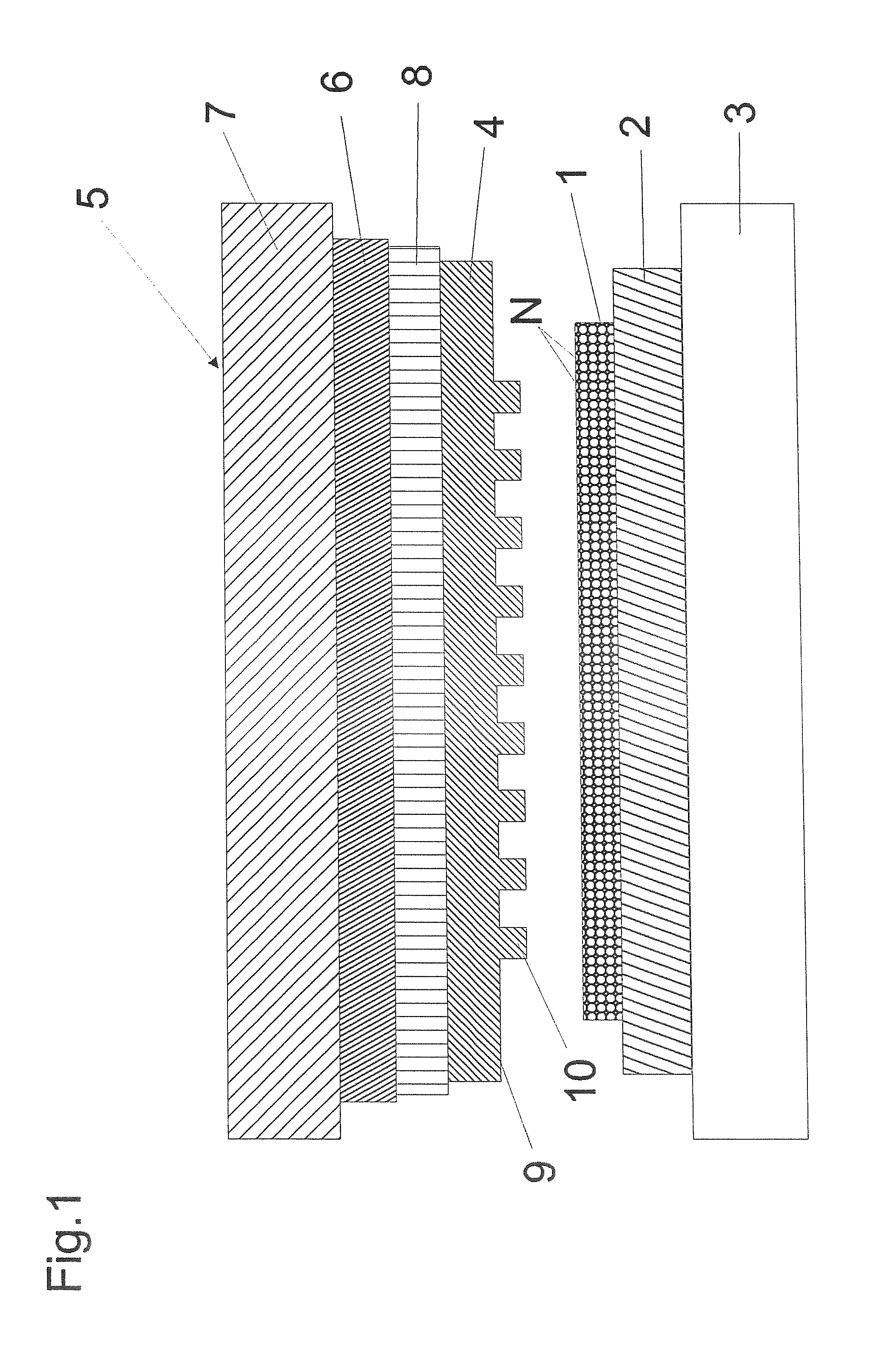
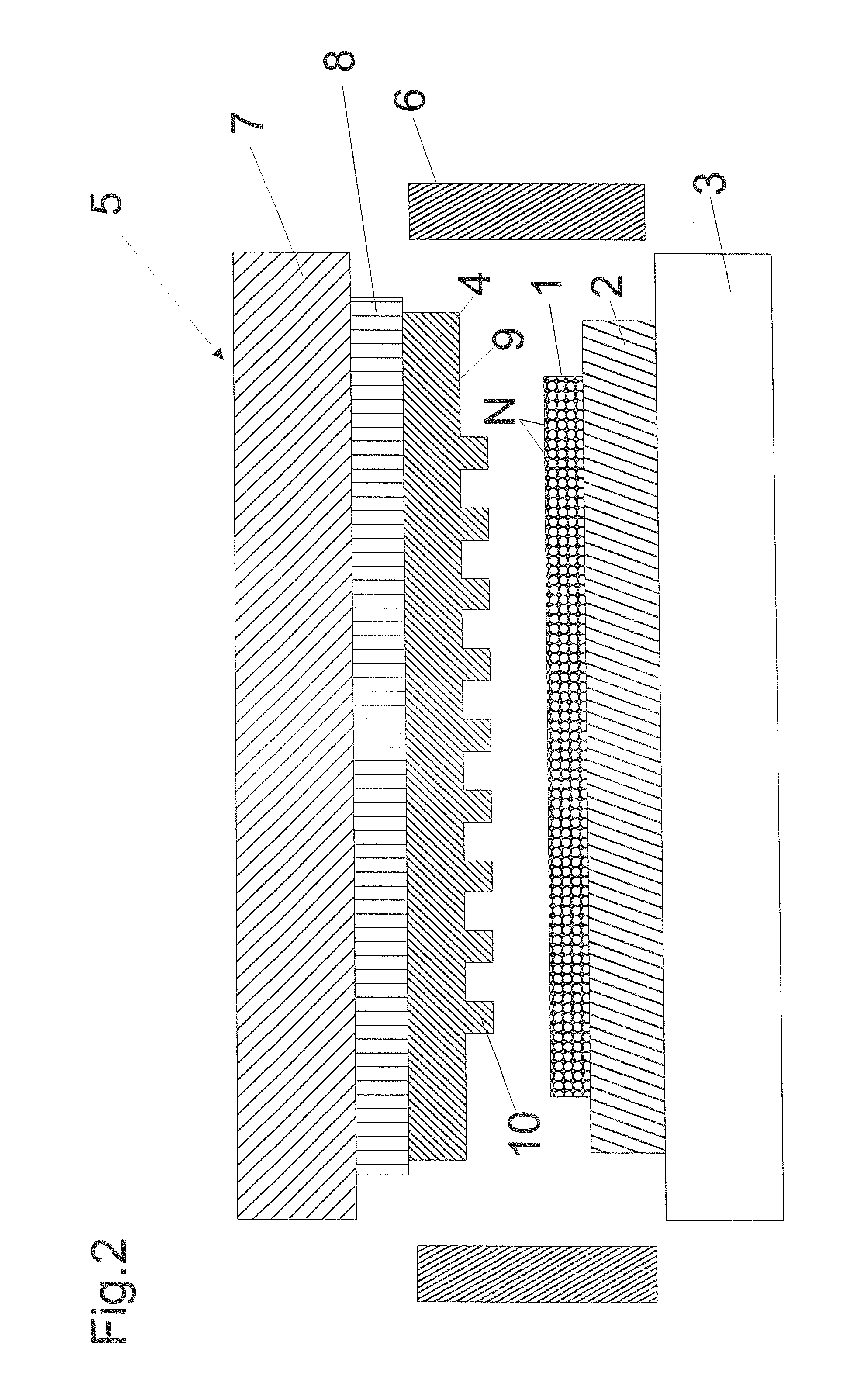
[0024]FIG. 1 shows a substrate 2 which is to be provided with a polymer layer 1 on a substrate holder 3. The substrate holder 3 can be a chuck and the substrate 2 is applied to the substrate holder 3 by a robot arm which is not shown and is unloaded again after application of the polymer layer 1.

[0025]The polymer layer 1 contains magnetic nanoparticles N which are distributed as uniformly as possible in the polymer layer 1.

[0026]The polymer layer 1 is applied or placed for example by spin lacquering, lamination or joining to the substrate during embossing or by inkjet methods.

[0027]Opposite the substrate holder 3 a pressure application means 5 is fixed on the device and the pressure application means 5 has a pressure cylinder 7 which can move an embossing die 4 which is attached to the pressure cylinder 7 in the direction of the substrate 2. The embossing die...


PUM

PropertyMeasurementUnit
Temperatureaaaaaaaaaa
Pressureaaaaaaaaaa
Magnetic fieldaaaaaaaaaa

Abstract

The invention relates to a device for hot embossing of a magnetic nanoparticle (N)-containing polymer layer and a method for hot embossing of a magnetic nanoparticle-containing polymer layer.

Description

FIELD OF THE INVENTION[0001]The invention relates to a device for hot embossing of a polymer layer and a method for hot embossing of a magnetic nanoparticle-containing polymer layer.BACKGROUND OF THE INVENTION[0002]In micro- and nanoengineering, hot embossing is used for transfer of a microscale or nanoscale pattern into a polymer layer. Here a flat substrate is first coated with a polymer and then is brought into contact with a prestructured die. Then the polymer is heated to liquefy it. The die is then pressed into the liquid polymer layer at a defined pressure. It is especially important to apply an embossing pressure which is as uniform as possible over the entire surface of the substrate. Then the polymer layer is molded by the die at a predefined temperature and cooled to room temperature.[0003]Hot embossing is used among others for producing micro-optical structures, microfluidic components and magnetic data media.[0004]Compared to photolithographic methods, the throughput fo...

Claims


Application Information

Patent Timeline
IPC IPC(8): B29C59/02
CPCB29C35/0272B29C59/02B29C2059/023B82Y10/00B29L2031/7562G03F7/0002B29C35/0288B29C59/022B82Y40/00
Inventor KAST, MICHAEL
Owner EV GRP E THALLNER GMBH
Why Eureka
Try Eureka