Point-to-multi-point transmission over a wired loop plant

a wired loop plant and multi-point technology, applied in the field of next-generation copper access, can solve the problems of untraditional application of p2mp to such networks, inefficient in terms of transmit power, and further obstacles to efficient implementation of p2mp access networks, and achieve the effect of efficient consumption of power

Active Publication Date: 2016-04-12
RPX CORP
View PDF27 Cites 0 Cited by
  • Summary
  • Abstract
  • Description
  • Claims
  • Application Information

AI Technical Summary

Benefits of technology

[0006]It is an object of the present invention to provide an original arrangement for support of P2MP transmission within an access node that is efficient both in terms of consumed power and individual data throughput available to each and every user.
[0017]The drawbacks of P2MP transmission over a wired loop plant are circumvented by introducing a switch between the transmitter and the links. The position of the switch is carefully designed to optimize power consumption and individual data throughputs, and minimize implementation difficulties. The solution includes a switching function to allow allocation of any lines to any one of multiple transceivers.

Problems solved by technology

Applying P2MP to such network is therefore untraditional.
This is very inefficient in terms of transmit power.
Moreover, the desire for reverse power feeding from customer premises and for Plain Old Telephony Service (POTS) add further obstacles for efficient implementation of P2MP access networks.
Thus the front end hardware needs to be able to transmit at very high powers, a factor of N higher than traditionally, which in turn imposes hard requirements on the performance and linearity of components such as the line driver.
Also, it is incompatible with the power budget constraints due to the reverse power feeding requirement.

Method used


Image

  • Point-to-multi-point transmission over a wired loop plant
  • Point-to-multi-point transmission over a wired loop plant
  • Point-to-multi-point transmission over a wired loop plant

Examples


Embodiment Construction

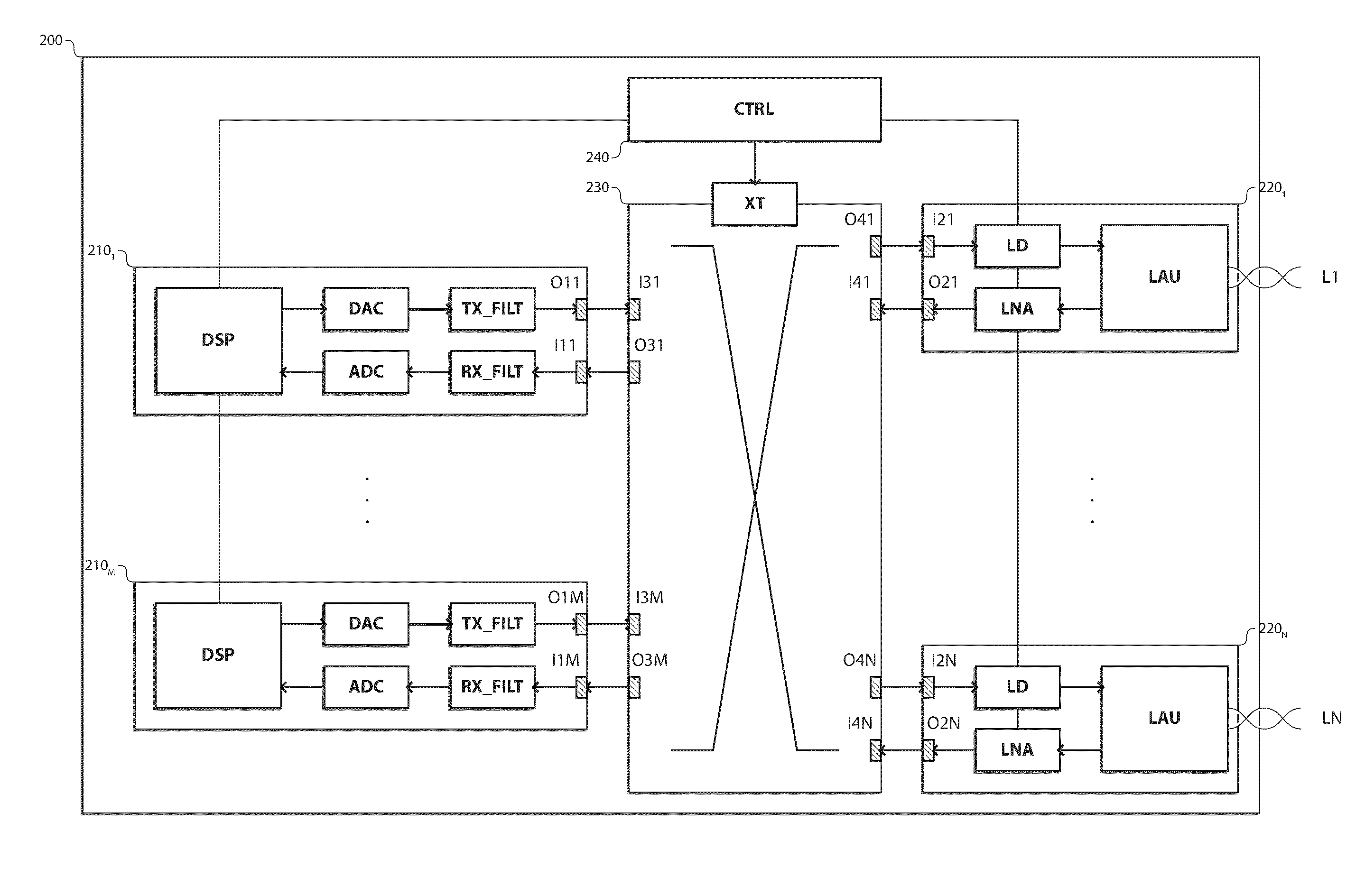
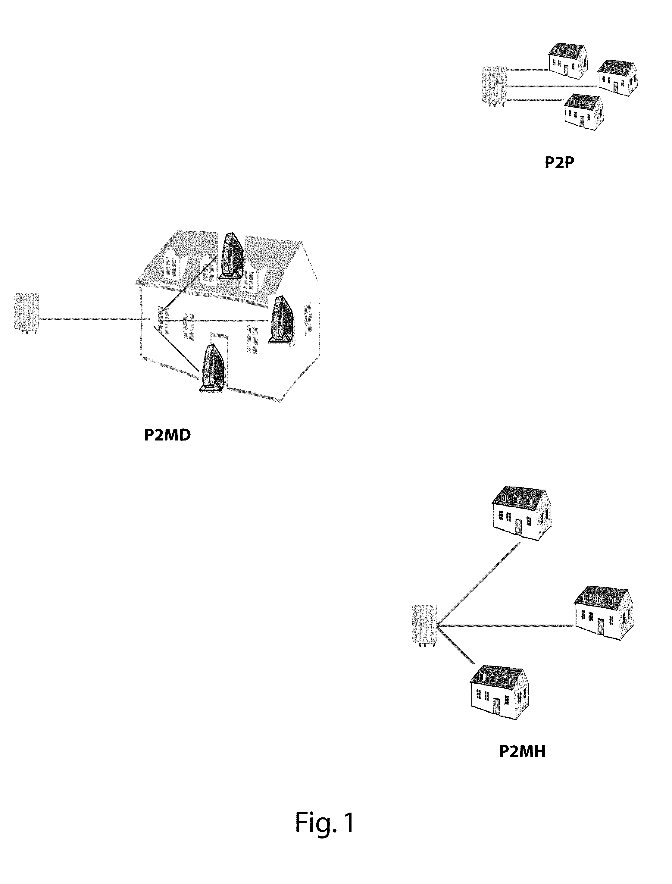
[0026]There is seen in FIG. 1 three access topologies: Point-to-Point (P2P), Point-to-Multi-Devices (P2MD), and Point-to-Multi-Home (P2MH).

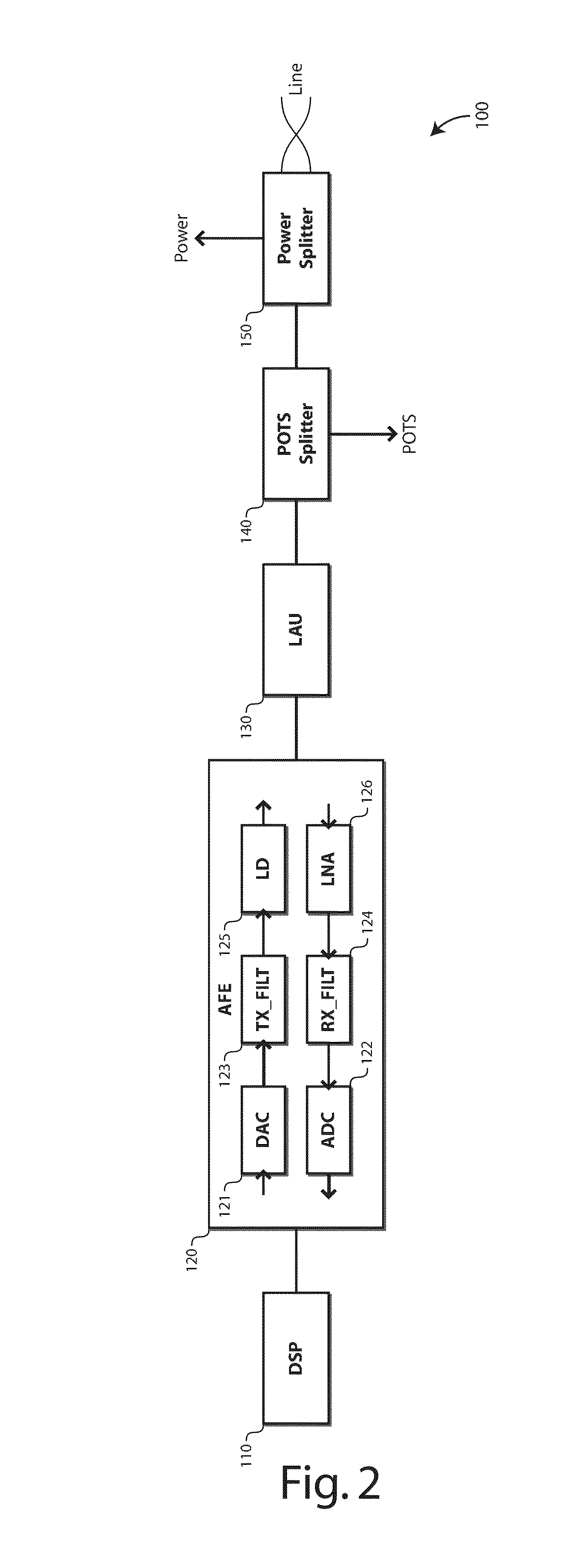
[0027][P2P] In the P2P use case, each subscriber is connected to a dedicated transceiver in the access node. Each subscriber has a single access network termination. This is the traditional approach in DSL (FIG. 1, top).

[0028]The advantage of this scheme is that each subscriber has its dedicated channel. This maximizes the capacity available for each subscriber and reduces the inter-dependencies between neighboring users. There is also a clear separation between the access and the in-home network, which allows a clear separation of management responsibilities.

[0029]One disadvantage is that a dedicated transceiver is required per end-user, with implications on access node size. Crosstalk is also a major issue. Crosstalk cancellation techniques, such as joint signal processing, can palliate this shortcoming.

[0030]Another disadvantage is that each s...


PUM


Abstract

The access node includes first transmit / receive circuitry with digital signal processing logic and digital-to-analog / analog-to-digital conversion logic, and second transmit / receive circuitry with transmit / receive amplifiers and line adaptation units for connection to a transmission line. The access node further includes an analog switch for dynamically connecting one of the first transmit / receive circuitry with one of the second transmit / receive circuitry according to a transmit / receive cross-connect table, and transmit / receive control logic for updating the transmit cross-connect table according to a transmit / receive traffic pattern over the respective transmission lines.

Description

CROSS-REFERENCE TO RELATED APPLICATIONS[0001]This application is the national phase under 35 U.S.C. §371 of PCT International Application No. PCT / EP2012 / 060475 which has an International filing date of Jun. 4, 2012, which claims priority to European patent application number 11305742.6 filed Jun. 14, 2011; the entire contents of each of which are hereby incorporated by reference.TECHNICAL FIELD OF THE INVENTION[0002]The present invention relates to next generation copper access, and more specifically to access nodes with point-to-multi-point transmission capabilities.TECHNICAL BACKGROUND OF THE INVENTION[0003]For next generation copper access, interest has been expressed in allowing Point-To-Multi-Point (P2MP) protocols. This has the claimed advantage that N users can be served from a single transceiver in the access node, with positive impact on cost, size, energy consumption and scalability of the access node.[0004]However, copper loop plants generally consist of dedicated (or poi...

Claims


Application Information

Patent Timeline
Patent Type & Authority Patents(United States)
IPC IPC(8): H04L12/18H04B3/00H04Q11/04H04J3/02H04L69/14
CPCH04B3/00H04Q11/04H04J3/02H04L12/18H04Q2213/13034H04Q2213/13107H04Q2213/13242H04Q2213/13396H04L25/02H04L5/22H04L69/14H04L61/00
Inventor MAES, JOCHENHOOGHE, KOEN
Owner RPX CORP
Why Eureka
Try Eureka