a discharge mechanism

A discharge mechanism and discharge port technology, applied in the direction of conveyor objects, transportation and packaging, roller tables, etc., can solve problems such as low efficiency and profile wear, achieve high efficiency and reduce labor costs

Active Publication Date: 2016-01-20
重庆立万精密部件有限公司
View PDF6 Cites 0 Cited by
  • Summary
  • Abstract
  • Description
  • Claims
  • Application Information

AI Technical Summary

Problems solved by technology

[0002] After the production and processing of round profiles such as steel pipes and pipes are completed, they need to be conveyed and unloaded through the discharge roller table. The traditional unloading step is completed by the feeding mechanism, but during the feeding process, due to friction between the feeding mechanism and the profile, Collision will easily cause the wear of the profile, and it needs to manually control the material shifting mechanism, so the efficiency is low

Method used


Image

  • a discharge mechanism
  • a discharge mechanism

Examples


Embodiment Construction

[0015] A discharge mechanism according to the present invention will be further described in detail through specific embodiments below.

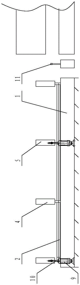
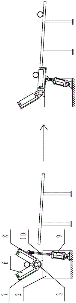
[0016] Such as figure 1 As shown, a discharge mechanism includes a conveying platform 1 arranged outside the discharge port, a base 2 is provided on the conveying platform 1, a central axis 3 is provided on the base 2, and two fixed shafts are arranged on the base 2. Roller 4 and two movable rollers 5, between the fixed roller 4 and the movable roller 5 are V-shaped settings, the fixed roller 4 and the movable roller 5 have the same structure, including a shell and a drum 6, and the drum 6 is movably arranged in the shell. One end of the fixed roller housing 7 is set at a fixed inclination angle and is fixedly connected with the central shaft 3. One end of the movable roller housing 8 is movably connected with the central shaft 3. The fixed roller 4 and the movable roller 5 cooperate with each other. The hydraulic cylinder that movable roll...


PUM


Abstract

The invention relates to a discharge mechanism which comprises a conveying platform arranged on the outer side of a discharge port, wherein a base is arranged on the conveying platform; at least two fixed rolls and at least two movable rolls are arranged on the base in an arraying manner; the fixed rolls and the movable rolls are arranged in a V shape; one end of each fixed roll is arranged in a fixed inclination angle manner, and fixed with the base; one end of each movable roll is movably connected with the base; the fixed rolls are matched with the movable rolls; driving devices used for driving the movable rolls to rotate are arranged on the conveying platform; and the position and the quantity of the driving devices correspond to those of the movable rolls. The discharge mechanism is suitable for conveying and blanking of circular sections.

Description

technical field [0001] The invention relates to the field of production and processing of circular profiles, in particular to a discharging mechanism. Background technique [0002] After the production and processing of round profiles such as steel pipes and pipes are completed, they need to be conveyed and unloaded through the discharge roller table. The traditional unloading step is completed by the feeding mechanism, but during the feeding process, due to friction between the feeding mechanism and the profile, Collision will easily cause the wear of the profile, and it needs to manually control the material shifting mechanism, so the efficiency is low. Contents of the invention [0003] The first technical problem to be solved by the present invention is to provide a discharge mechanism that can make the profile not easily damaged. [0004] In order to solve the first technical problem above, the technical solution adopted by the present invention is: a discharge mecha...

Claims


Application Information

Patent Timeline
Patent Type & Authority Patents(China)
IPC IPC(8): B65G13/02B65G47/42
Inventor 朱德云何波
Owner 重庆立万精密部件有限公司
Why Eureka
Try Eureka