Control method of soundproof door

A control method and sound-proof door technology, which is applied to the arrangement of sound-proof doors/windows, door leaves, wing leaves, etc., can solve the problems of affecting the sound insulation effect, laborious opening and closing of the door, and rubber ring wear, so as to improve the sound insulation effect and reduce wear and tear , the effect of prolonging the service life

Inactive Publication Date: 2020-09-08
董雪霞
View PDF1 Cites 0 Cited by
  • Summary
  • Abstract
  • Description
  • Claims
  • Application Information

AI Technical Summary

Problems solved by technology

[0008] In order to solve the above-mentioned technical problems, the present invention provides a sound-proof door structure for noise control, to solve the problem that the door gap of the existing sound-proof door is usually fixed with a ring of sealing rings inside the door frame or outside the door body when performing sound insulation treatment. The sound-proof rubber ring can play the role of sealing and sound insulation, but when opening and closing the door, the friction between the door body or the door frame and the rubber ring is relatively large, it is more laborious to open and close the door, and the rubber ring is also more likely to cause wear and tear. The locking devices of the glottis are also installed inside the door body, because the thickness of the door body is mostly thin, and the part where the locking device is installed takes up more space on the door body, which affects the sound insulation effect of this part

Method used


Image

  • Control method of soundproof door
  • Control method of soundproof door
  • Control method of soundproof door

Examples


Embodiment

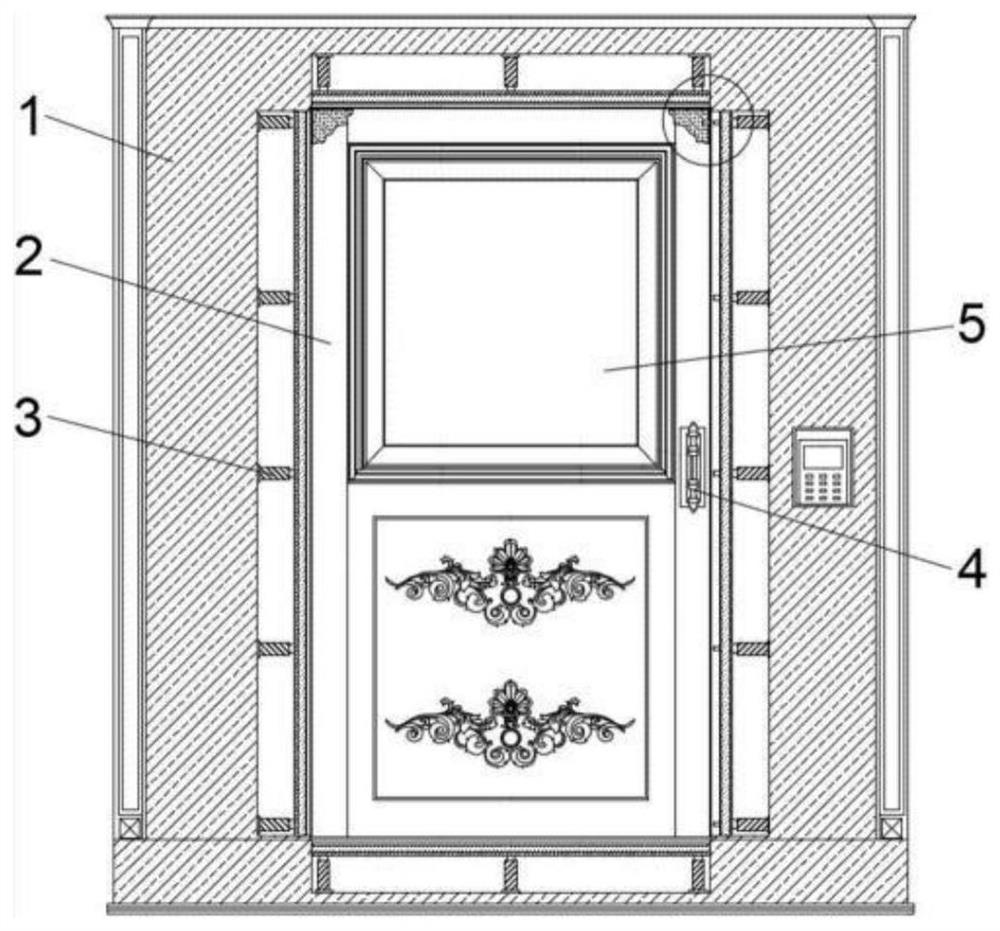
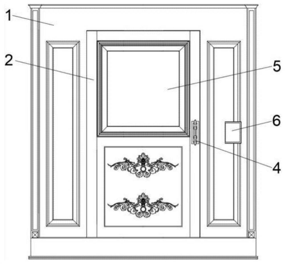
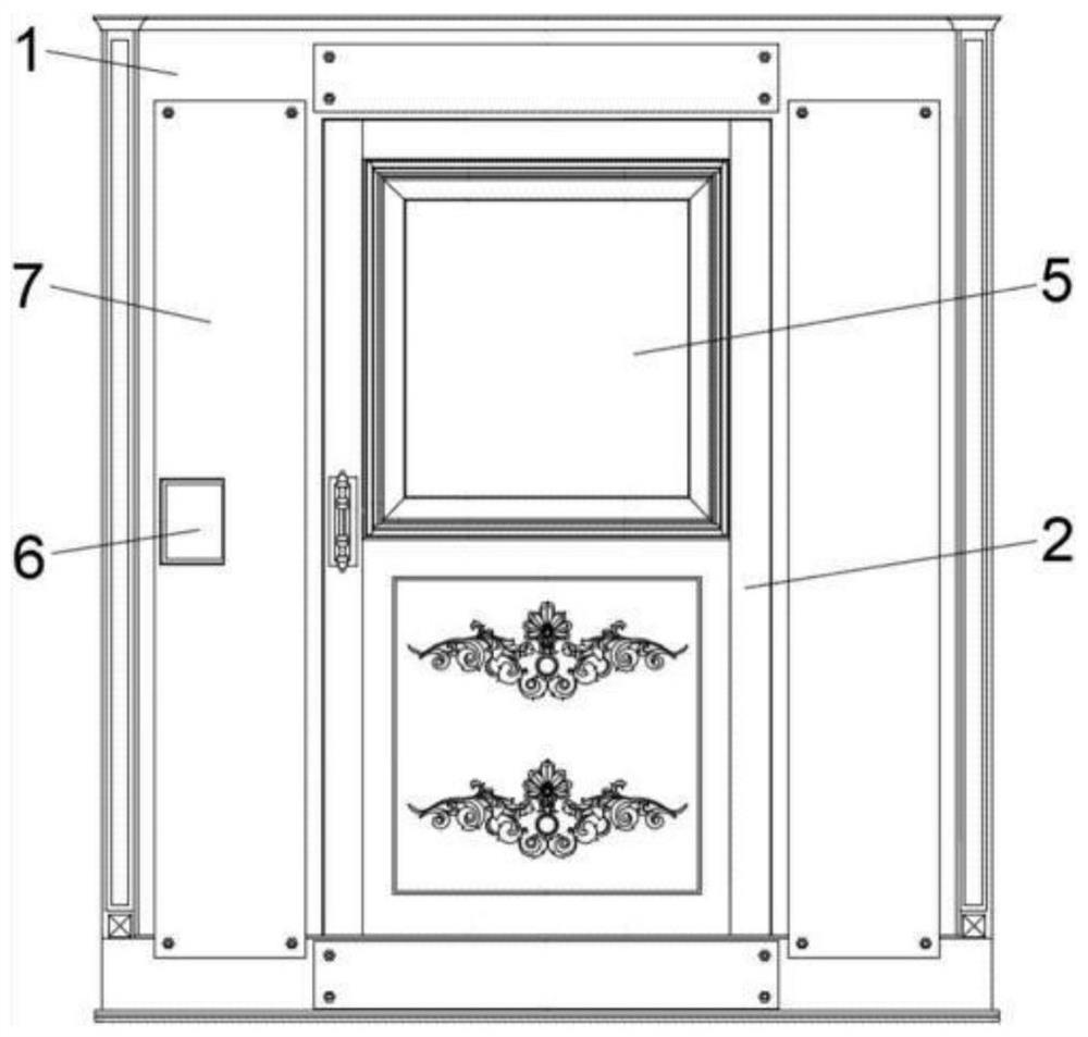
[0035] as attached figure 1 to attach Figure 8 Shown:

[0036] The present invention provides a sound-insulating door structure for noise control, including a door frame 1, a main door body 2, sound-absorbing cotton 201, PU202, a mineral wool sound-insulating board 203, an electric push rod 3, a door handle 4, a sound-insulating glass 5, a control Switch 6, maintenance cover plate 7, support steel plate 8, soundproof felt strip 9, clip strip 10 and lock block 11;

[0037]A main door body 2 is installed on the inner side of the door frame 1 through a rotating shaft; the main door body 2 is composed of two layers of sound-absorbing cotton 201, two layers of PU202 and one layer of mineral wool sound insulation board 203; the inner side of the main door body 2 is also fixedly installed with A piece of soundproof glass 5; the front and rear sides of the main door 2 are also fixed with a door handle 4; the inner side of the door frame 1 and the inner side of the top and the inner...


PUM


Abstract

The invention provides a control method of a soundproof door. The soundproof door comprises a door frame, a main door body and lock blocks; and the main door body is movably installed on the inner side of the door frame through a rotary shaft. By arranging soundproof felt strips, the reduction of the abrasion of soundproof strips is facilitated; a control switch of one side on which a user is located is firstly pressed when the user passes through the soundproof door, so that the control switch controls four groups of electric push rods to drive a supporting steel plate and the soundproof feltstrips to move to the outer side, and clamping strips and the locking blocks can be separated from the outer side of the main door body; then the main door body can be rotated and pushed, the user repeatedly presses the control switch on the other side after passes through the soundproof door, and the control switch can repeatedly control the four groups of electric push rods to push the supporting steel plate and the soundproof felt strips to move to the inner side; and then the clamping strips can be repeatedly embedded into a groove of the outer side of the main door body, the effects of sealing and sound proofing are achieved, the soundproof felt strips cannot rub against the main door body, labor is relatively saved when the door is opened and closed, the soundproof felt strips cannot be worn, and the service life is prolonged.

Description

[0001] This application is a divisional application of a Chinese invention patent application with the application number 201810418437.5 filed on July 25, 2018, and the title of the invention is a sound insulation door structure for noise control. technical field [0002] The invention belongs to the technical field of noise prevention and control, and more specifically relates to a method for controlling an acoustic door. Background technique [0003] Acoustic doors are widely used in studios, theaters, broadcasting studios, sound engineers, cinemas, anechoic rooms, audiometry rooms, machine rooms, sound insulation enclosures, factories and other occasions that require noise control. Among them, the door gap between the door frame and the door leaf can directly affect the sound insulation effect of the sound insulation door. The greater the sound insulation value of the sound insulation door, the greater the impact of the door gap; the experiment shows that when the sound in...

Claims


Application Information

Patent Timeline
Patent Type & Authority Applications(China)
IPC IPC(8): E06B5/20E06B3/36E06B3/70E06B7/30E06B7/22E06B7/18
CPCE06B3/36E06B3/70E06B5/20E06B7/18E06B7/22E06B7/30
Inventor 董雪霞张壮朱琳
Owner 董雪霞
Why Eureka
Try Eureka