A method for predicting the abrasiveness of different drilling directions in shale formations

An abrasive, shale technology, applied in earth-moving drilling, wellbore/well components, etc., can solve the problems of large manpower, material resources and funds, lack of data contrast, and difficulty in obtaining rock abrasiveness data, etc. Field application, the effect of saving the cost of downhole coring

Active Publication Date: 2016-04-06
CHINA UNIV OF PETROLEUM (BEIJING)
View PDF7 Cites 1 Cited by
  • Summary
  • Abstract
  • Description
  • Claims
  • Application Information

AI Technical Summary

Problems solved by technology

[0004] These methods are all indoor experimental methods, and there are many problems, such as: ① The obtained results are difficult to reflect the high temperature and high pressure environment of the rock underground; ② It is difficult to fully reflect the change of rock properties in heterogeneous formations; The data measured in areas with large lithology changes may lack contrast; ④ It is difficult to establish a continuous section of rock abrasiveness in the area, and it is difficult to obtain rock abrasiveness data in different drilling directions; ⑤ It costs a lot of manpower, material resources and funds

Method used


Image

  • A method for predicting the abrasiveness of different drilling directions in shale formations
  • A method for predicting the abrasiveness of different drilling directions in shale formations
  • A method for predicting the abrasiveness of different drilling directions in shale formations

Examples


Embodiment Construction

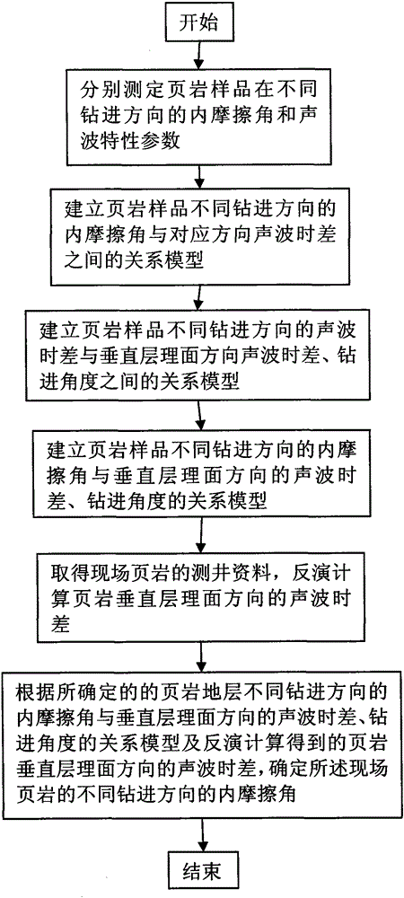
[0022] Such as figure 1 As shown, the method for predicting the abrasiveness of different drilling directions in shale formations includes the following steps:

[0023] Step 1, respectively measure the internal friction angle and acoustic wave characteristic parameters of shale samples in different drilling directions; the specific methods are as follows:

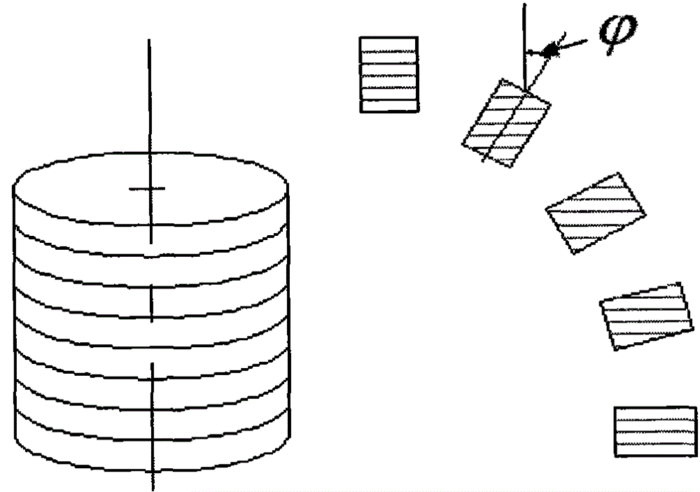
[0024] Collect shale samples from many different areas, such as collecting shale samples from multiple oil fields; in order to ensure the relationship between the internal friction angle of the determined shale samples in different drilling directions and the acoustic wave characteristic parameters in the direction perpendicular to the bedding plane To be representative and extensive, it is necessary to collect as many rock samples as possible from as many different locations as possible.

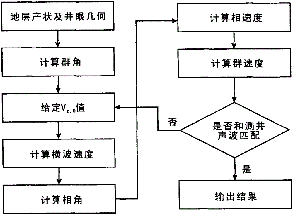
[0025] After the rock samples were collected, the acoustic time difference of each shale sample was measured in different bedding plan...


PUM


Abstract

The invention relates to a method for predicting the abrasiveness of a shaly stratum in different drilling directions. The method comprises the following steps: (1) measuring the internal friction angles and the sonic characteristic parameters of shale samples in different drilling directions; (2) building the relation models between the internal friction angles and the sonic time differences of the shale samples in different drilling directions; (3) building the relation models between the sonic time differences of the shale samples and the sonic time differences in the direction perpendicular to bedding planes as well as between the sonic time differences and drilling angles; (4) building the relation models between the internal friction angles of the shale samples in different drilling directions and the sonic time differences in the direction perpendicular to the bedding planes as well as between the internal friction angles and the drilling angles; (5) obtaining the logging data of on-site shale and performing back calculation to the sonic time differences of the shale in the direction perpendicular to the bedding planes; and (6) according to the relation models between the internal friction angles and the sonic time differences in the direction perpendicular to the bedding planes as well as between the internal friction angles and the drilling angles, determining the internal friction angles of the on-site shale in different drilling directions. The determined internal friction angles are the abrasiveness in corresponding drilling directions. The method can evaluate the abrasiveness of the shaly stratum in different drilling directions by virtue of the on-site sonic logging data and is convenient to use on site.

Description

technical field [0001] The invention belongs to the field of petroleum drilling, and in particular relates to a method for predicting abrasiveness in different drilling directions of shale formations. Background technique [0002] In the fields of oil exploration, extraction, and the like, well drilling is widely performed. Drilling is the process of drilling into rock formations using a drill bit. During the drilling process, the drill bit becomes blunt due to the wear of the rock and needs to be replaced after a period of use. The abrasiveness of the rock is an important factor affecting the wear of the drill bit. For shale formations with obvious bedding anisotropy, it is of great significance to accurately grasp the abrasiveness of different drilling directions in drilling engineering, such as bit selection, drilling parameter optimization, and directional wellbore trajectory optimization design. . [0003] Abrasiveness of rock is the ability of the rock to wear away...

Claims


Application Information

Patent Timeline
Patent Type & Authority Patents(China)
IPC IPC(8): E21B49/00
Inventor 张辉高德利苗侠
Owner CHINA UNIV OF PETROLEUM (BEIJING)
Why Eureka
Try Eureka