Steel ball surface quality detection system

A surface quality and detection system technology, applied in the direction of material magnetic variables, etc., can solve the problems of high processing cost, low efficiency, steel balls entering the market, etc., to improve efficiency and accuracy, avoid steel balls stuck, and improve accuracy Effect

Active Publication Date: 2013-09-18
SHANDONG UNIV OF SCI & TECH
View PDF4 Cites 9 Cited by
  • Summary
  • Abstract
  • Description
  • Claims
  • Application Information

AI Technical Summary

Problems solved by technology

As the core component of the steel ball surface quality testing equipment, the unfolding wheel is particularly easy to damage and needs to be replaced regularly, resulting in high maintenance costs
The steel ball rolls on the vertical surface under the rubbing of the upper and lower unfolding wheels of the detection mechanism, and it is inevitable to approach one side in the ball socket, that is, the steel ball must stick to the inner surface of the ball socket during the detection process. The position in the ball socket is also random, and the size of the defect or crack on the surface of the steel ball (including the length and depth of the crack) ranges from 0.001mm to 0.1mm, which is necessary for a very high-precision eddy current sensor. Cracks on the surface of the detector are very fatal, but the detection structure of the existing technology can hardly detect them, and it is easy to cause unqualified steel balls to flow into the market
Moreover, the structure of the sorting and feeding mechanism in the prior art is complicated, the processing cost is high, the efficiency is low, and the situation that steel balls are often stuck is prone to occur.

Method used


Image

  • Steel ball surface quality detection system
  • Steel ball surface quality detection system
  • Steel ball surface quality detection system

Examples


Embodiment Construction

[0024] The present invention provides a steel ball surface quality detection system. In order to make the purpose, technical solution and effect of the present invention more clear and definite, the present invention will be further described in detail below. It should be understood that the specific embodiments described here are only used to explain the present invention, and are not intended to limit the present invention

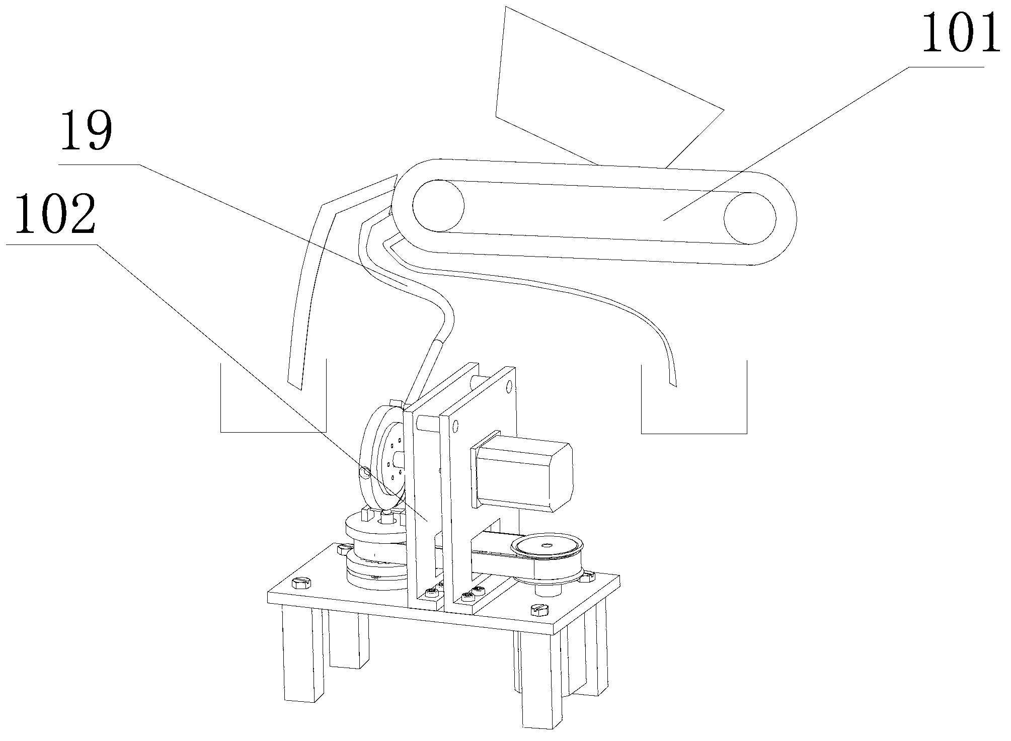
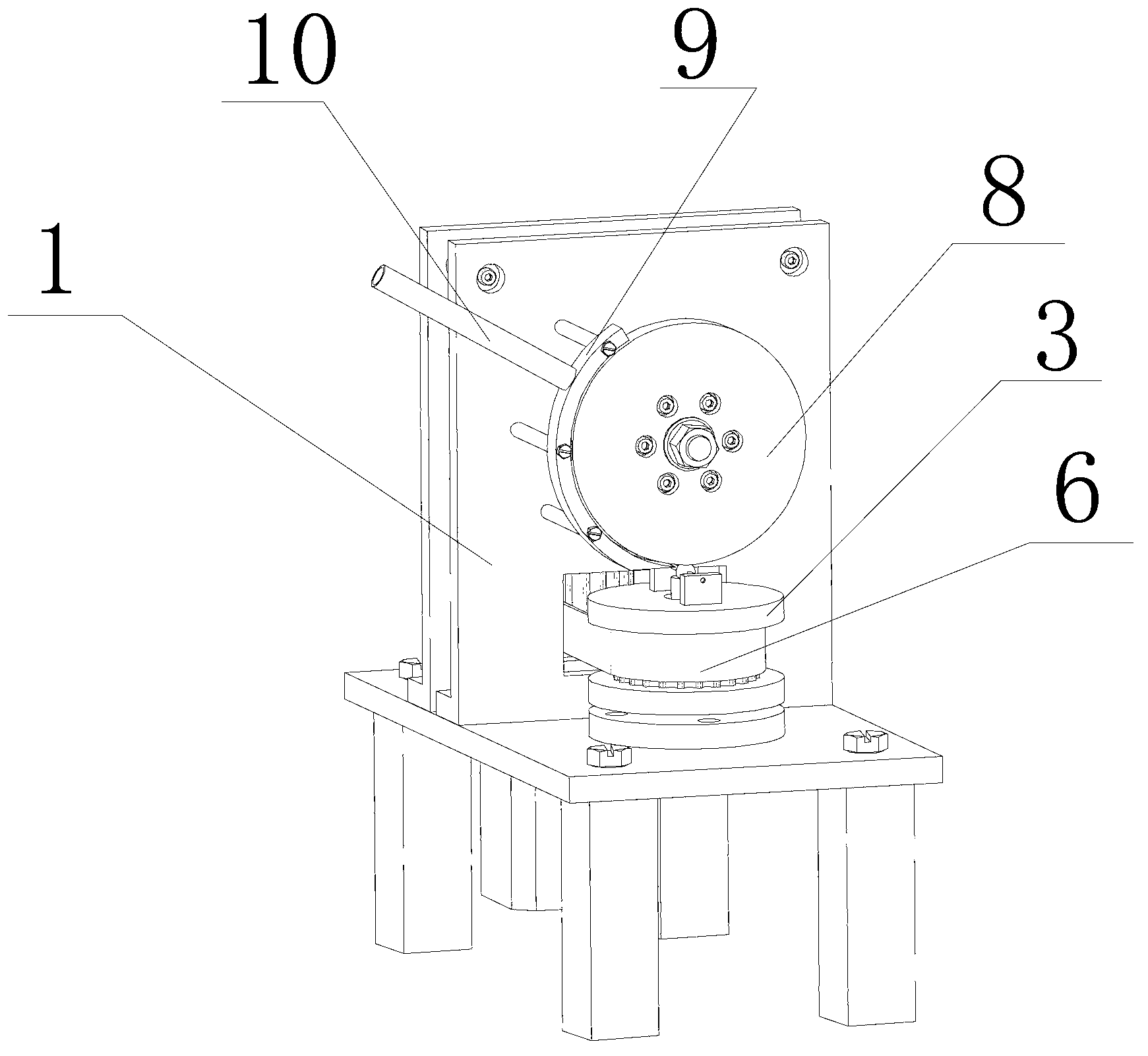
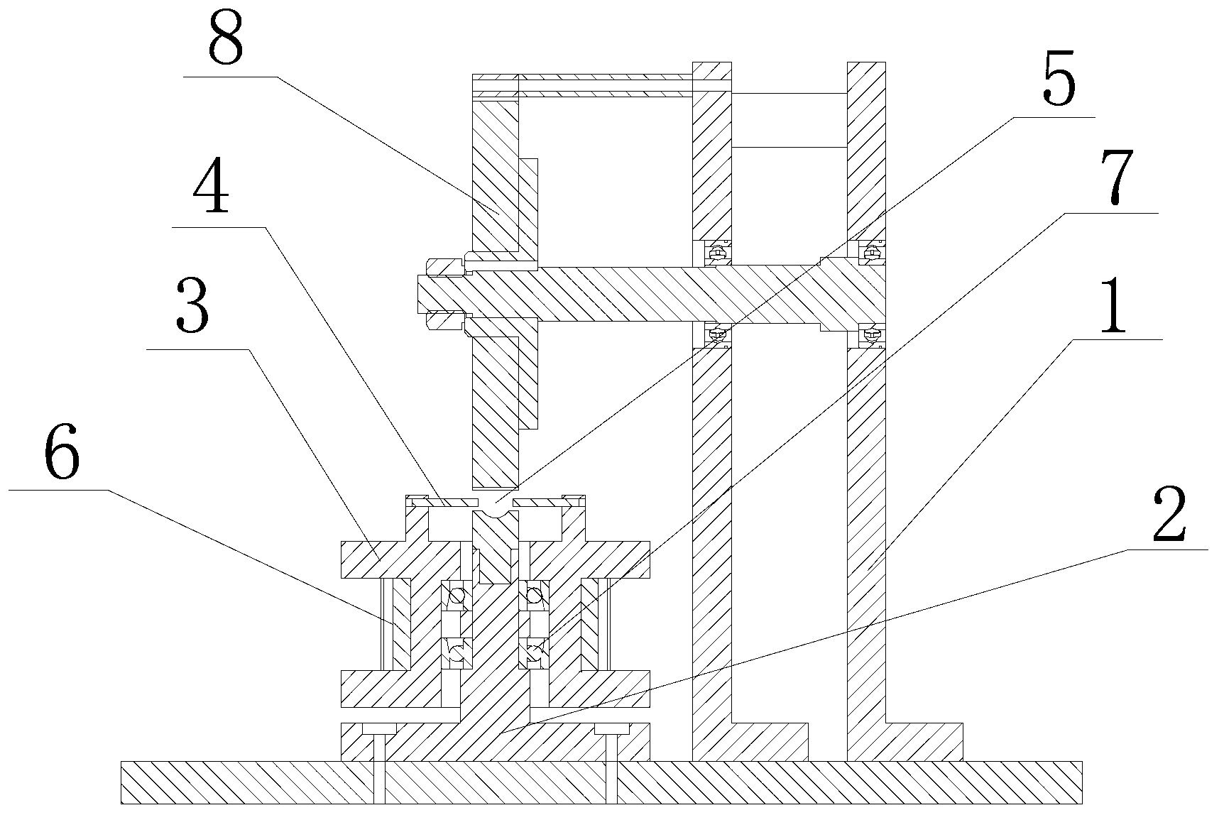
[0025] The invention provides a steel ball surface quality detection system, such as figure 1 , figure 2 and image 3 As shown, it includes a sorting mechanism 101 and a detection mechanism 102, the sorting mechanism 101 is located above the detection mechanism 102, and is used to provide the detection mechanism 102 with steel balls to be detected, and the detection mechanism 102 Including a frame 1, which includes a frame 1, the frame 1 is provided with an inner support 2, and the inner support 2 is provided with a rotatable eddy current detection su...


PUM


Abstract

The invention discloses a steel ball surface quality detection system. The system comprises a sorting mechanism and a detection mechanism, wherein the sorting mechanism is arranged above the detection mechanism and used for providing a to-be-detected steel ball having standard diameter for the detection mechanism, wherein the detection mechanism comprises a frame, an inner bracket is arranged on the frame, the inner bracket is provided with a rotatable eddy current detection bracket, the eddy current detection bracket is provided with an eddy current detection probe, a detection cavity for placing the steel ball is formed by the eddy current detection bracket and the upper end of the inner bracket, the eddy current detection bracket is capable of rotating around the detection cavity, and an expanding structure for leading rubbing and finally discharging the steel ball is arranged above the detection cavity. The sorting mechanism and the detection mechanism are scientifically and reasonably improved so as to improve the efficiency and the accuracy of selecting the steel ball, the problems that the steel ball is blocked in the selecting process and the centre of the steel ball is tenderly moved in the detection process are avoided, and the precision of the steel ball detection is improved.

Description

technical field [0001] The invention relates to the field of steel ball surface quality detection, in particular to a steel ball surface quality detection system. Background technique [0002] Among the steel ball surface quality testing equipment, AVIKO series steel ball surface quality testing equipment is widely used in the world at present. This equipment adopts the meridian expansion method to realize the complete expansion of steel ball surface defects. As the core component of the steel ball surface quality testing equipment, the unrolling wheel is particularly easy to damage and needs to be replaced regularly, resulting in high maintenance costs. The steel ball rolls on the vertical surface under the rubbing of the upper and lower unfolding wheels of the detection mechanism, and it is inevitable to approach one side in the ball socket, that is, the steel ball must stick to the inner surface of the ball socket during the detection process. The position in the ball so...

Claims


Application Information

Patent Timeline
Patent Type & Authority Applications(China)
IPC IPC(8): G01N27/90
Inventor 张华宇谢凤芹杨前明丁鸿昌陈必胜孔祥强
Owner SHANDONG UNIV OF SCI & TECH
Why Eureka
Try Eureka