Improved glasses legs, colloid injection manufacturing method and die equipment

A technology of spectacle legs and injection method, which is applied in the directions of glasses/goggles, optics, instruments, etc., can solve the problems of increased cost, low work efficiency, troubles, etc., and achieve the effects of improving production efficiency, increasing yield, and ensuring the accuracy of card installation

Inactive Publication Date: 2013-09-18
宏懋金属制品(深圳)有限公司
View PDF5 Cites 1 Cited by
  • Summary
  • Abstract
  • Description
  • Claims
  • Application Information

AI Technical Summary

Problems solved by technology

[0021] The problem with the existing technology is that there is a very critical process in the production process, which is the clamping process. In this process, the positioning piece must be set on the position corresponding to the tail of the foot wire, and then the positioning piece should be clamped. In the socket of the positioning piece at the bottom of the groove of the temple on the mold of the temple, at the same time, the head of the wire is lapped on the boss in the groove of the temple, so that the wire is suspended and positioned on the place. In the groove of the spectacle legs mentioned above, the problem brought by this method is that it is very troublesome to put the positioning piece on the foot wire, and the operator needs to be very careful to operate it carefully, and the work efficiency is extremely low. The grooves of the temples are deflected, resulting in waste products. Furthermore, for the temples produced in this way, the positioning piece will remain on the temple permanently. Although the positioning piece is not too large, it will not affect the overall appearance of the temple, but At least it is still necessary to arrange a special process in the follow-up process to process the part of the positioning piece exposed on the temple of the glasses, resulting in an increase in cost. According to the above, it is obvious that the existing technology needs further improvement

Method used


Image

  • Improved glasses legs, colloid injection manufacturing method and die equipment
  • Improved glasses legs, colloid injection manufacturing method and die equipment
  • Improved glasses legs, colloid injection manufacturing method and die equipment

Examples


Embodiment Construction

[0062] In the following, the present invention will be further described in conjunction with an improved spectacle leg and colloid injection manufacturing method, mold equipment and accompanying drawings provided by the preferred embodiments of the present invention.

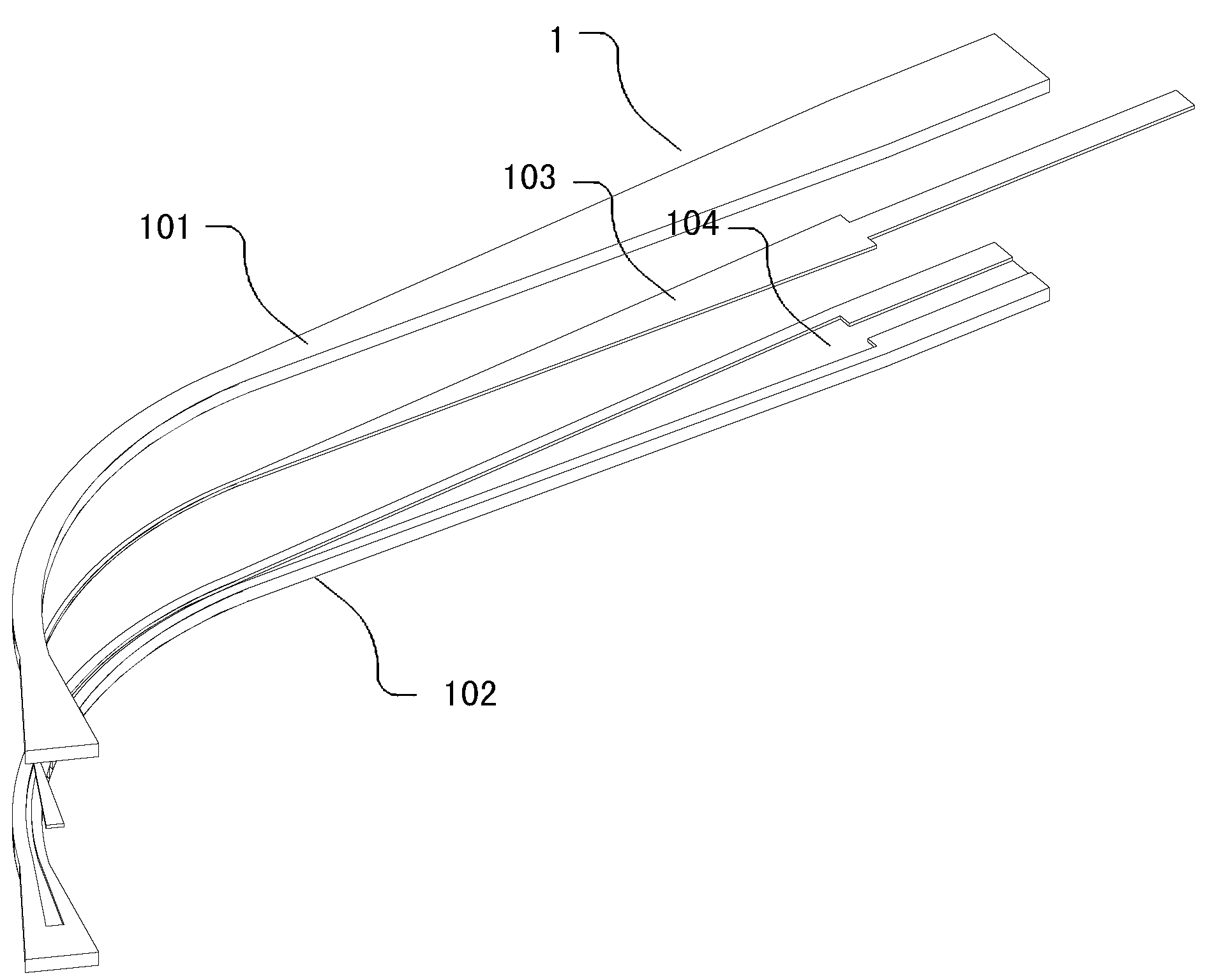
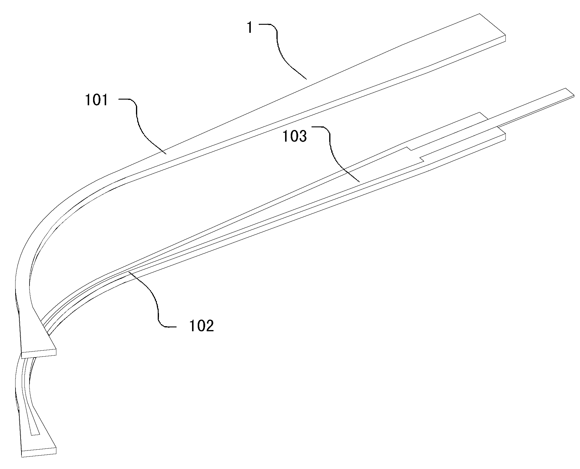
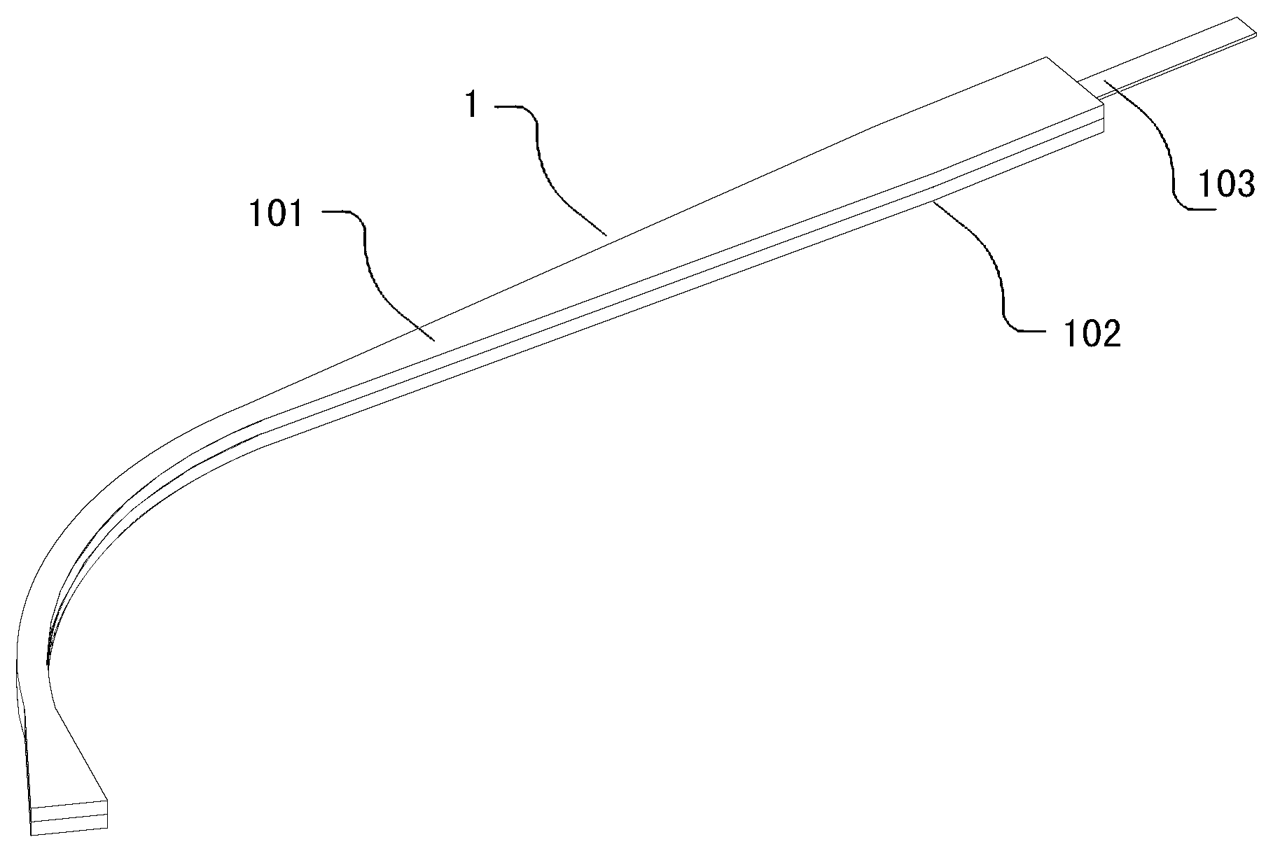
[0063] An improved spectacle leg of the present invention, as attached figure 1 , attached figure 2 , attached image 3 As shown, it includes temples 1 and wires 103, and the wires 103 are located in the temples 1. The point is that the temples 1 include upper pieces 101 and lower pieces 102 of temples, and also include wires Accommodating cavity, in this preferred embodiment, a leg wire receiving groove 104 is formed on the lower part 102 of the temple. The upper piece 101 of the glasses temple will cover the leg wire receiving groove 104, and after the leg wire receiving groove 104 is covered, the said wire wire embedded fitting accommodation cavity will be formed, and the said wire wire 103 will be located...


PUM


Abstract

The invention discloses improved glasses legs, a colloid injection manufacturing method and die equipment. Each improved glasses leg is characterized by comprising a glasses leg upper sheet and a glasses leg lower sheet, and also comprising a leg wire containing cavity, wherein the leg wire containing cavity consists of leg wire containing grooves of the glasses leg upper sheet and / or the glasses leg lower sheet; a leg wire is positioned in the leg wire embedding containing cavity; the glasses leg upper sheet and the glasses leg lower sheet are integrated through an adhesive layer; the die equipment comprises the glasses leg containing cavity, a liquid colloid injection channel and a vacuumizing channel; the method comprises the following steps of: injecting liquid colloid, vacuumizing the liquid colloid injection channel, and solidifying the liquid colloid by a liquid colloid solidifying technology. According to the invention, the problems of complex production technology and low yield of conventional glasses legs in the prior art are solved.

Description

technical field [0001] The invention relates to an eyeglass leg, in particular to an improved eyeglass leg, its colloid injection manufacturing method and its production mold equipment. Background technique [0002] With the rapid development of social technology, the continuous improvement of people's culture and living standards, and the development of vision care work, glasses are playing an increasingly important role in people's life. In our daily life, glasses are protective The necessities of the eyes, on the other hand, is also a kind of decoration; and the spectacle legs are an important part of the glasses, especially with the development of glasses jewelry, fashion, beautiful colors and elegant appearance have become the pursuit of the majority of young people. An important standard. While pursuing comfort, people also have higher and higher requirements for its beauty. The glasses legs in the form of built-in wires have incomparable advantages of conventional gla...

Claims


Application Information

Patent Timeline
Patent Type & Authority Applications(China)
IPC IPC(8): G02C5/14B29C39/10B29C39/42
Inventor 崔广
Owner 宏懋金属制品(深圳)有限公司
Why Eureka
Try Eureka