Automatic transaction device and method for preventing card information from being stolen for automatic transaction device
An automatic transaction device, medium reading technology, applied in the direction of a complete banking system, a complete banking system, coin-free or similar appliances, etc. Effect
- Summary
- Abstract
- Description
- Claims
- Application Information
AI Technical Summary
Problems solved by technology
Method used
Image
Examples
Embodiment 1
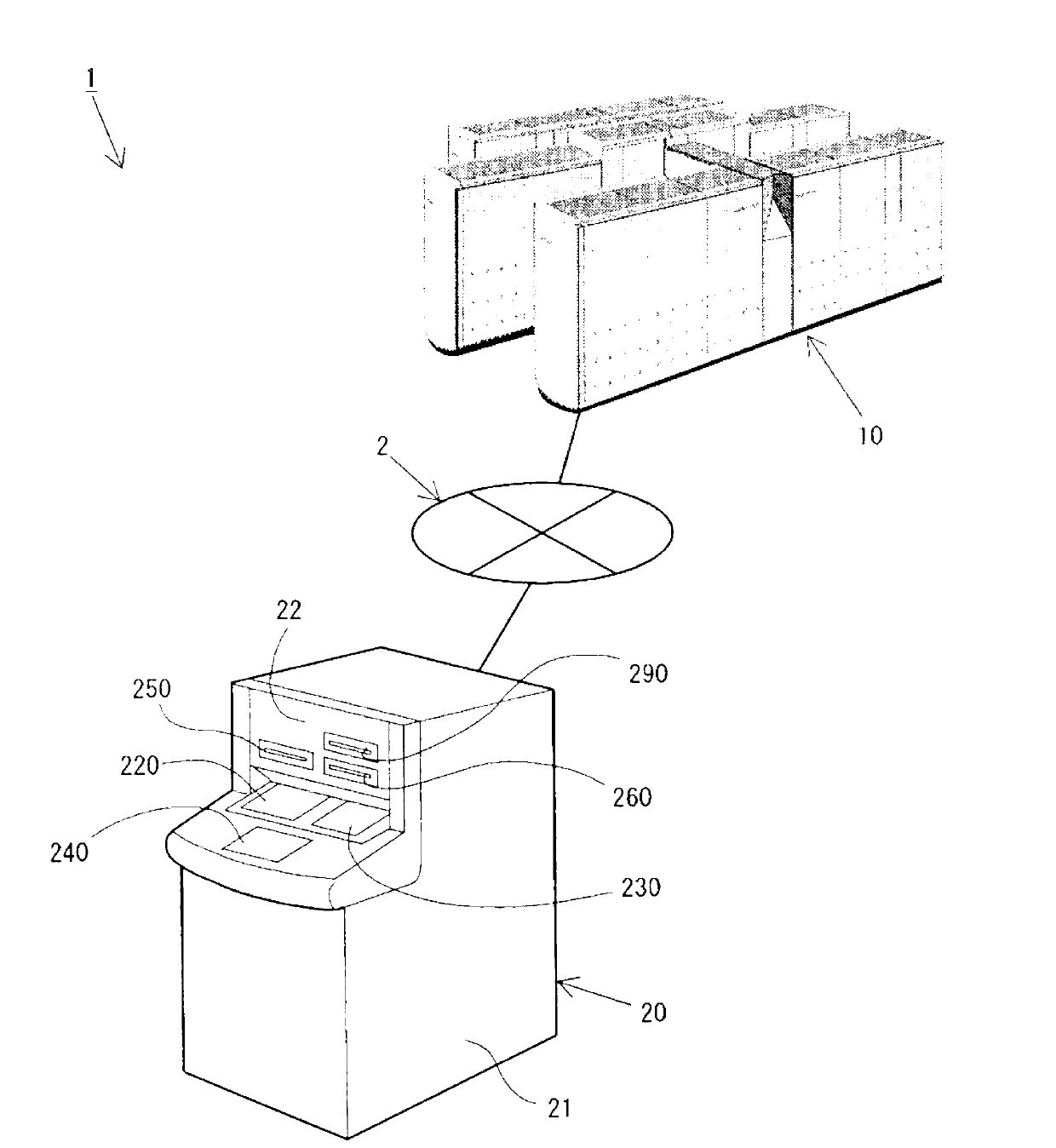
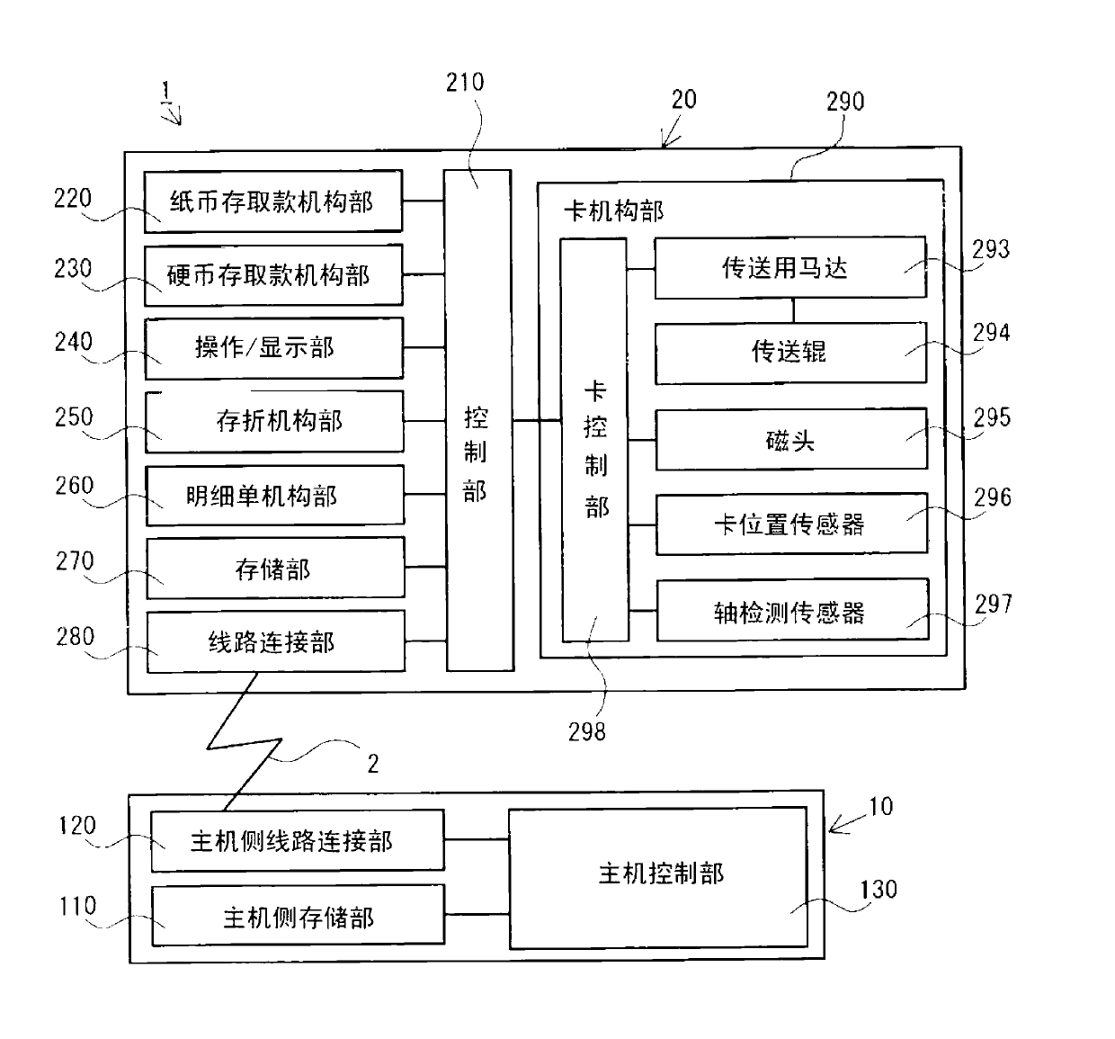
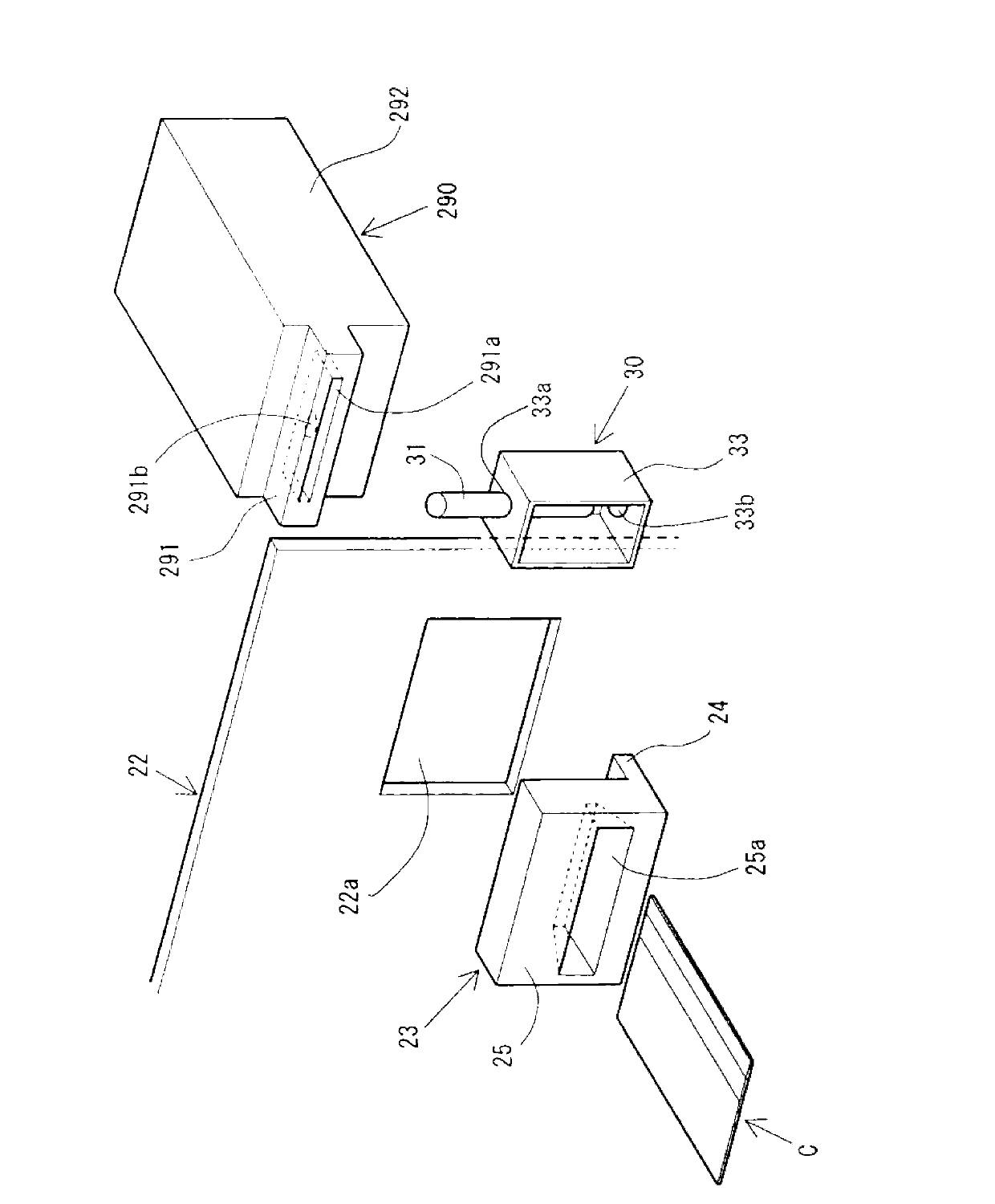
[0059] First, use Figure 1 to Figure 4 The automatic trading system 1 in this embodiment will be described in detail.
[0060] in addition, figure 1 A structural diagram of an automatic trading system 1 is shown, figure 2 A block diagram showing the internal structure in the automatic trading system 1, image 3 It shows a perspective view of the appearance of the card mechanism part 290, the decorative panel 23 and the closing unit 30, Figure 4 A side cross-sectional view of the card mechanism portion 290 , the decorative panel 23 and the closing unit 30 is shown.
[0061] Automated trading system 1 such as figure 1 As shown, it is comprised from the host computer 10 and the ATM20 (automatic transaction apparatus) connected to the host computer 10 via the communication line 2.
[0062] The communication line 2 is constituted by a LAN line, an Internet line, and the like.
[0063] The host computer 10 is installed in the same store as the ATM 20 or in a remote head off...
Embodiment 2
[0148] Next, use Figure 10 An example in which the structure and arrangement of the closed cells are different from the above-mentioned example 1 will be described.
[0149] in addition, Figure 10 An explanatory diagram illustrating the operation of the closing unit 50 (conveyance path closing member) in Embodiment 2 is shown, Figure 10 (a) shows the state where the decorative panel 26 (closing preventing member) is installed, Figure 10 (b) shows the state in which the card data trapping device S is installed.
[0150] In addition, the same structures as those of Embodiment 1 described above are given the same reference numerals and detailed description thereof will be omitted.
[0151] The closed unit 50 in embodiment 2 is as Figure 10 As shown in (a), it has the closing shaft 51 (protruding member), the electromagnetic solenoid driver 52 (driver), and the surrounding member 53 (surrounding member).
[0152] The closing shaft 51 has a substantially cylindrical shape...
Embodiment 3
[0182] Next, use Figure 11 and Figure 12 An example in which the structure of the closing unit is different from the above-mentioned example 1 will be described.
[0183] in addition, Figure 11 An explanatory diagram illustrating the operation of the closing unit 60 (conveyance path closing member) in Embodiment 3 is shown, Figure 12 A flowchart showing the operation of the startup processing in the third embodiment. also, Figure 11 (a) shows the state where the decorative panel 23 is attached, Figure 11 (b) shows the state in which the card data trapping device S is installed.
[0184] In addition, the same structures as those of Embodiment 1 described above are given the same reference numerals and detailed description thereof will be omitted.
[0185] Such as Figure 11As shown in (a), the closing unit 60 in Example 3 has a closing shaft 61 (protruding member), an electromagnetic solenoid driver 62 (driver), a coil spring 63 (elastic member), and a surrounding ...
PUM
 Abstract
Description
Claims
Application Information
 - R&D
- Intellectual Property
- Life Sciences
- Materials
- Tech Scout
- Unparalleled Data Quality
- Higher Quality Content
- 60% Fewer Hallucinations
Browse by: Latest US Patents, China's latest patents, Technical Efficacy Thesaurus, Application Domain, Technology Topic, Popular Technical Reports.
© 2025 PatSnap. All rights reserved.Legal|Privacy policy|Modern Slavery Act Transparency Statement|Sitemap|About US| Contact US: help@patsnap.com


