

Method for supporting broadcast data continuity
A broadcast data and continuity technology, applied in broadcast service distribution, electrical components, wireless communication, etc., can solve the problem that there is no way for the serving cell to obtain the service area indication of the adjacent frequency, so as to reduce complexity and information The effect of interaction
- Summary
- Abstract
- Description
- Claims
- Application Information
AI Technical Summary
Problems solved by technology
Method used
Image

Examples
Embodiment 1
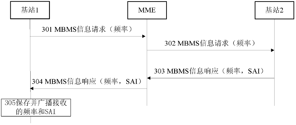
[0064] Embodiment 1 describes that through the S1 interface, the base station requests to obtain the service area indicator SAI list corresponding to a certain frequency of the neighboring base station, and the neighboring base station sends the SAI corresponding to the frequency to the requesting base station. Such as image 3 shown. The method may include the steps of:
[0065] Step 301: Base station 1 sends a message "MBMS information request" to MME, requesting to obtain the SAI list corresponding to the specific frequency of adjacent base station 2.
[0066] The base station 1 can obtain the cell identity and the frequency of the cell on the adjacent base station through the automatic neighbor cell establishment process, and discover a new cell. The process is as follows: the serving cell of the UE is the cell on the base station 1, the UE detects the information of the surrounding cells, and sends the detected physical cell identities of the surrounding cells to the se...
Embodiment 2
[0076] Embodiment 2 describes that through the S1 interface, the base station requests to obtain the SAI list corresponding to all the frequencies on the neighboring base station, and the neighboring base station sends the SAIs corresponding to all the frequencies on the base station to the requesting base station. Such as Figure 4 shown. The method may include the steps of:
[0077] Step 401: Base station 1 sends a message "MBMS information request" to MME, requesting to obtain the SAI list corresponding to all frequencies of adjacent base station 2.
[0078] The base station 1 can obtain the cell identifier and the frequency of the cell on the adjacent base station through the automatic neighbor cell establishment process, and discover a new cell. The process is as follows: the serving cell of the UE is the cell above the base station 1, the UE detects the information of the surrounding cells, and sends the detected physical cell identities of the surrounding cells to the...
Embodiment 3
[0093] Embodiment 3 describes that through the S1 interface, the base station sends the SAIs corresponding to all its frequencies to neighboring base stations, and the neighboring base station sends the SAIs corresponding to all its frequencies to the requesting base station. Such as Figure 5 shown. The method may include the steps of:
[0094] Step 501: Base station 1 sends a message "MBMS information request" to MME, requesting to obtain the SAI lists corresponding to all frequencies of adjacent base station 2.
[0095] The base station 1 can obtain the cell identifier and the frequency of the cell on the adjacent base station through the automatic neighbor cell establishment process, and discover a new cell. The process is as follows: the serving cell of the UE is the cell above the base station 1, the UE detects the information of the surrounding cells, and sends the detected physical cell identities of the surrounding cells to the serving cell. If the information of t...
PUM
 Abstract
Description
Claims
Application Information