Knitting method of fabric by flatbed knitting machine

A technology for knitted fabrics and flat knitting machines, which is applied to weft knitting, flat knitting machines with individual moving needles, and knitting, and can solve problems such as rising device costs, complicated devices, and increased use of knitting threads

Inactive Publication Date: 2013-09-25
SHIMA SEIKI MFG LTD
View PDF8 Cites 4 Cited by
  • Summary
  • Abstract
  • Description
  • Claims
  • Application Information

AI Technical Summary

Problems solved by technology

[0010] If the loose eye row portion 9b is lengthened to apply a lowering force on the outside of the knitting width before approaching, stable knitting can be performed, but the amount of knitting yarn used for the long loose eye row portion 9, 9b increases. , will increase the cost of production
In order to be able to use the needle setting device again in the flat knitting machine when the short pine eye course portion 9a is needled from the middle of the knitting of the body piece 7, a technique of retracting the lowering roller 6 has also been proposed, but the device Complicated, increasing device cost

Method used


Image

  • Knitting method of fabric by flatbed knitting machine
  • Knitting method of fabric by flatbed knitting machine
  • Knitting method of fabric by flatbed knitting machine

Examples


Embodiment 1

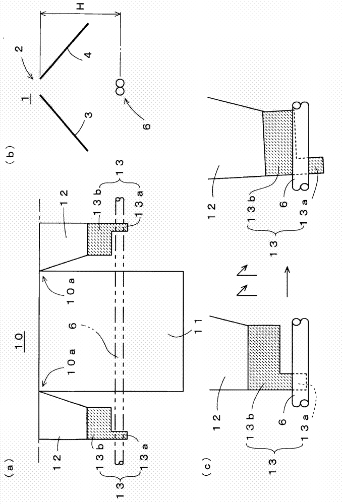
[0035] figure 1In (a), as Embodiment 1 of the present invention, the state in which the joint knitting method of knitted fabric according to the present invention is applied to the knitted fabric 10 is simplified and shown, and in (b), the knit used for knitting is shown in simplified form. The structure of the flatbed knitting machine 1 is shown in simplified form, and (c) shows the effect when joint knitting is performed by the pine-eye course portion 13 . In Embodiment 1 of the present invention, the knitwear 10 is also woven as a tubular knitted fabric in which the sleeves 12 are separated on both sides of the body 11, and joined when reaching the armpit 10a to form a tubular body. Then, in order to reduce the diameter of the cylindrical body, approaching is performed to narrow the knitting width. The weaving and knitting of the knitted fabric 10 itself formed by such weaving Figure 4 The knitwear 5 of (b) is performed in the same manner.

[0036] That is, if figure ...

Embodiment 2

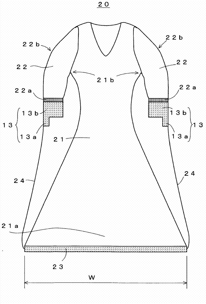
[0045] image 3 The simplified structure of the knitted fabric 20 to which the joint knitting method of the knitted fabric according to Example 2 of the present invention is applied is shown. The body part 21 which becomes the basic knitted fabric of the knit fabric 20 has the shape which continues integrally with the skirt part 21a which hem spreads. At least the lower end side of the skirt portion 21a is knitted using a range W that is a wide range of needle beds 3 and 4, and the range W includes a segment for knitting the sleeve 22 that is shorter than the body 21. The pine eye course portion 13 starts knitting within the range W of the needle bed section used for knitting the skirt portion during knitting of the body 21 . The sleeves 22 to be the additional knitted fabric are knitted from the cuff opening 22a continuous with the pine eye course part 13, and are joined to the body part 21 after knitting in parallel until the body part 21 is knitted to the underarms 21b. A...


PUM


Abstract

There is provided a knitting method of a fabric by a flatbed knitting machine that makes it possible to decrease a separation knitting part and perform stable knitting even when lengths of sleeves are smaller than that of a body of a knitted wear or the like. A knitted wear 10 is knitted as a tubular knitted fabric, for which sleeves 12 are knitted as separated tubular knitted fabrics at both sides of a body 11, when the sleeves 12 reach to underarm portions 10a, they are joined to the body 11 so as to form one tubular body, and then performs to move stitch for narrowing a knitting width so as to decrease a diameter of the tubular body. When starting to move stitch, as shown in (c), the lower ends of the separation knitting parts 13 at the side of the outer end portions can be taken down by a take down roller 6. The lower ends of the separation knitting parts 13 are not uniform and the small width portions 13a thereof at the sides of the outer end portions are longer, so that the separation knitting parts 13 can be caught by the tale down roller 6 reliably in a state of being inclined outward.

Description

technical field [0001] The present invention relates to a knitting method of a knitted fabric by a flat knitting machine, which repeats approaching and stitch formation for reducing the integrated knitting width after joining a plurality of knitted fabrics by the flat knitting machine. Background technique [0002] Conventionally, for knitwear such as a knitted pullover, the body and both sleeves are knit under the armpit as tubular knitted fabrics using a flat knitting machine, and then the body and both sleeves are joined together. Since the diameter of such joined cylindrical body becomes larger, the sleeve side is brought closer to the body side, the stitches are overlapped, and new stitches are formed by knitting continuously with the overlapped stitches, thereby reducing the knitting width while reducing the knitting width. Continue weaving (for example, see Patent Document 1). [0003] Figure 4 (a) The basic structure of the flat knitting machine 1 used for joint kn...

Claims


Application Information

Patent Timeline
Patent Type & Authority Applications(China)
IPC IPC(8): D04B1/24
CPCD04B1/246D04B1/24D04B7/32
Inventor 奥野昌生
Owner SHIMA SEIKI MFG LTD
Why Eureka
Try Eureka