Point-connected curtain wall fixture
A curtain wall and fixture technology, which is applied in the field of point-to-point curtain wall connection devices, can solve the problems of increasing and decreasing the number of glass curtain wall panels.
- Summary
- Abstract
- Description
- Claims
- Application Information
AI Technical Summary
Problems solved by technology
Method used
Image

Examples
Embodiment 1
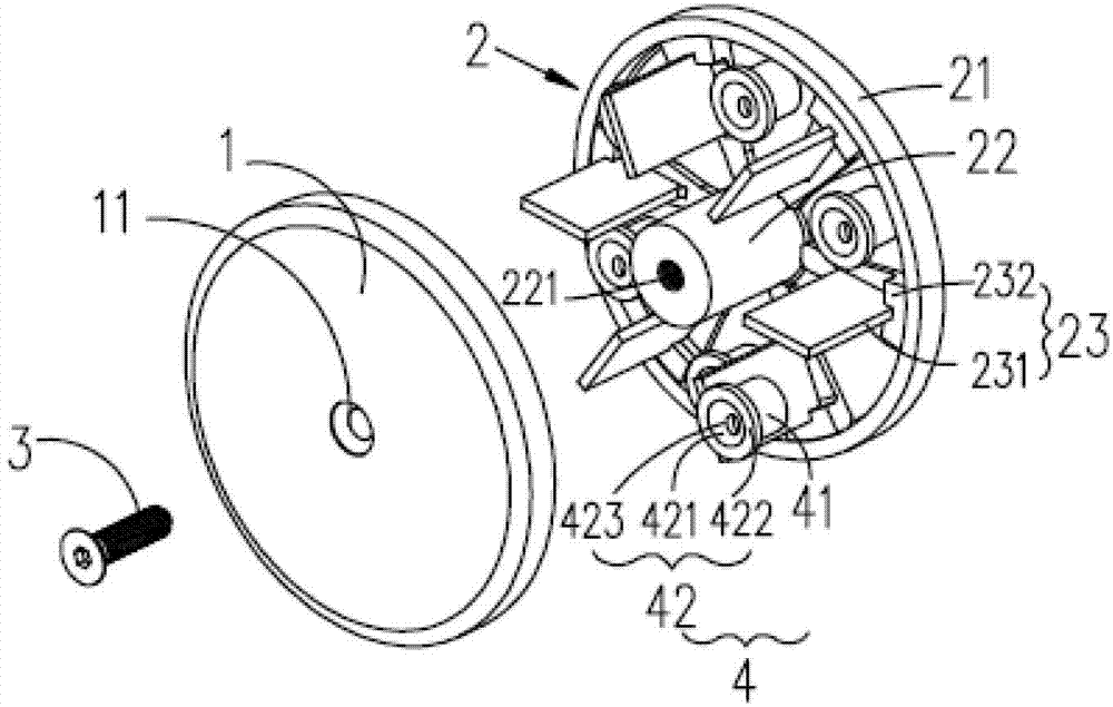
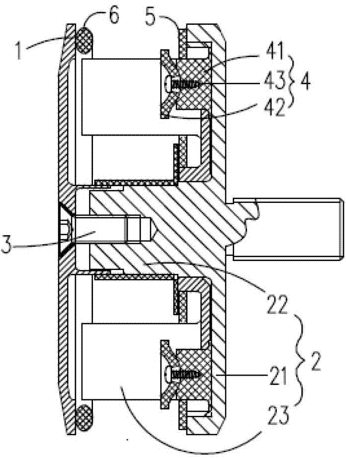
[0061] Such as Figures 1A to 1C As shown, the point-jointed curtain wall fixture of the first embodiment of the present invention includes an outer clamping plate 1, an inner clamping seat 2, a bolt 3, a plurality of spherical joint structures (six in this embodiment) 4, gaskets 5 and thick Install gasket 6.
[0062] The outer splint 1 is a circular plate, and of course other shapes can be adopted according to the owner's requirements or design requirements; the center of the outer splint 1 is provided with a mounting hole 11 penetrating the outer splint from the inside to the outside.
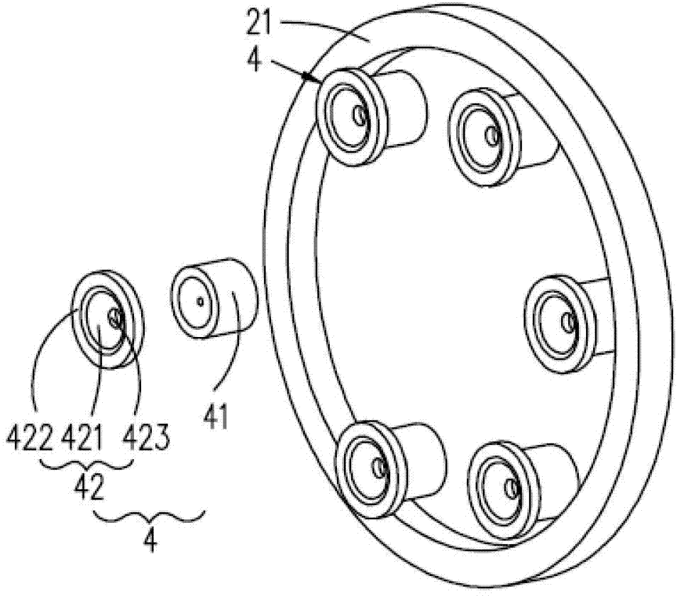
[0063] The inner clamping seat 2 includes an inner clamping plate 21, a mounting seat 22 and a partition structure 23;
[0064]The inner splint 21 is a circular plate that matches the outer splint 1, and of course other shapes can be adopted according to the requirements of the owner or the design requirements. The outer splint 1 and the inner splint 21 shown in the figure have the same peri...
Embodiment 2
[0070] The structure of this embodiment is basically the same as that of Embodiment 1, the difference is:
[0071] There is no positioning hole 423 on the spherical surface 421 of the ball joint spacer 42, and the ball joint spacer 42 is directly placed on the ball joint base 41 to form a ball joint connection. During installation, through the cooperation of the curtain wall panel and the fixture, the ball joint spacer The sheet 42 is pressed onto the ball hinge base 41;
[0072] The inner splint 21 extends along the circumferential direction of the inner splint 21 and is provided with a partially annular screw mounting groove 211. The ball joint structure 4 also includes a base positioning screw 44. The base positioning screw 44 penetrates from the inner end surface of the inner splint 21 to the outer end surface. The screw mounting groove 211 on the splint 21 is screwed to the ball joint base 41 to install the ball joint structure 4 on the inner splint 21 .
[0073] In this...
Embodiment 3
[0075] The structure of this embodiment is basically the same as that of Embodiment 1, the difference is:
[0076] The outer peripheral edge of the inner splint 21 is provided with a tooth structure 212 toward the direction of the outer splint 1;
[0077] The ball hinge base 41 includes a base positioning block 411, a tooth structure 412 and a ball hinge seat body 413; the base positioning block 411 is matched with the inner splint 21 and the partition base 232 into a partial fan shape; the outer peripheral edge of the base positioning block 411 is matched to the The tooth structure 212 of the inner splint 21 is provided with a tooth structure 412; the inner end surface of the ball joint seat body 413 is fixed on the base positioning block 411, and the outer end surface of the ball joint seat body 413 is matched with the ball joint gasket 42 to form a concave shape. Spherical surface (partial spherical surface); the tooth structure 411 of the spherical hinge base 41 meshes wit...
PUM
 Abstract
Description
Claims
Application Information
 - R&D
- Intellectual Property
- Life Sciences
- Materials
- Tech Scout
- Unparalleled Data Quality
- Higher Quality Content
- 60% Fewer Hallucinations
Browse by: Latest US Patents, China's latest patents, Technical Efficacy Thesaurus, Application Domain, Technology Topic, Popular Technical Reports.
© 2025 PatSnap. All rights reserved.Legal|Privacy policy|Modern Slavery Act Transparency Statement|Sitemap|About US| Contact US: help@patsnap.com