Vertical connecting sleeve suitable for building

A technology for connecting sleeves and buildings, which is applied in the direction of building structures, buildings, building components, etc., can solve the problems of increasing PM2.5 in the environment, low manufacturing efficiency, and difficulty in realization, so as to be easy to promote and use, and meet the installation positioning , the overall structure is simple

Pending Publication Date: 2019-05-21
昆山征途建筑模架应用技术有限公司
View PDF0 Cites 0 Cited by
  • Summary
  • Abstract
  • Description
  • Claims
  • Application Information

AI Technical Summary

Problems solved by technology

[0004] At the same time, the existing grouting sleeves on the market include casting of ductile iron, machining of medium carbon steel round rods or forging of steel pipes. They have a common feature, that is, the threaded part and the grouting part of the sleeve are integrated. It is very difficult, and the utilization rate of materials is low, especially the sleeves machined from ductile iron and medium carbon steel round rods on the market. The outer surface of the sleeve is smooth and cannot form a good mesh with concrete. Grouting sleeve The protruding process on the inner wall is complicated, the grouting part of the grouting sleeve is very deep, the processing is difficult, and the manufacturing efficiency is low. Preliminary statistics show that the material utilization rate of the grouting sleeve formed by machining the medium carbon steel round bar is only 50%. Left and right, nodular cast iron can only use the foundry casting process in the casting process, so some of the products will inevitably have pores and sand inclusions inside, which will affect the strength of the product. As far as the casting process is concerned, the increase in environmental PM2.5 has a certain impact direct impact
[0005] Some people proposed to forge the steel pipe, add grooves and protrusions, but because it is a one-time forming, the processing is very difficult
Basically, it is difficult to achieve, so there is no such product widely used in the market

Method used


Image

  • Vertical connecting sleeve suitable for building
  • Vertical connecting sleeve suitable for building

Examples


Embodiment Construction

[0025] The specific implementation manners of the present invention will be further described in detail below in conjunction with the accompanying drawings and embodiments. The following examples are used to illustrate the present invention, but are not intended to limit the scope of the present invention.

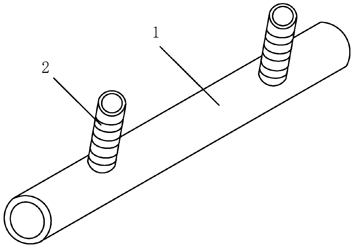
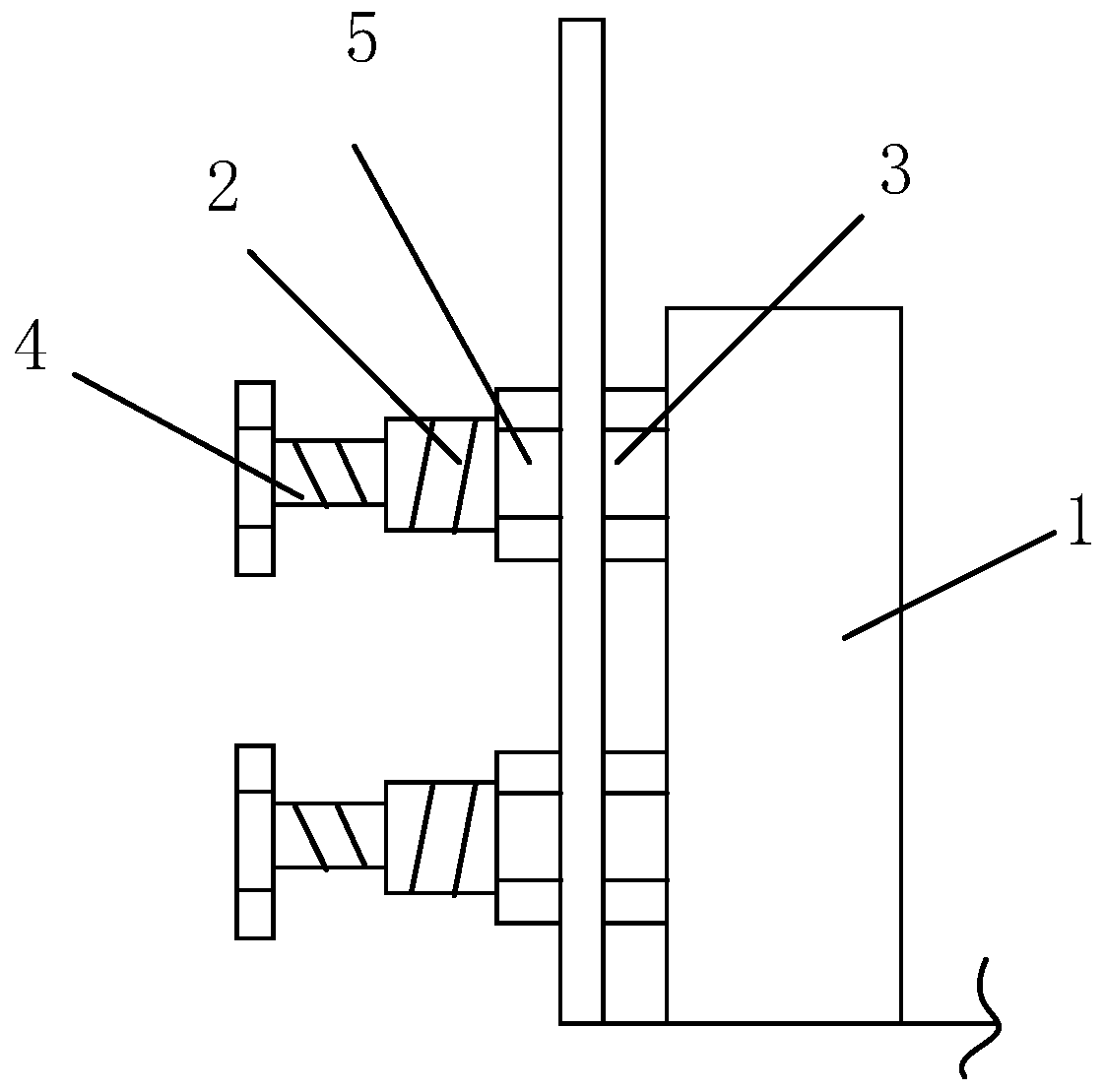
[0026] Such as figure 1 , figure 2 A vertical connection sleeve suitable for buildings includes a sleeve body 1, which is different in that: one side of the sleeve body 1 is provided with at least two vertically collinear connection components 2. At the same time, considering that during actual use, it can ensure that the present invention has an appropriate joint gap after being installed in place, which is convenient for subsequent grouting operations. Moreover, in order to carry out effective clamping connection and apply continuous inward stress to the sleeve body 1 , a jacking bolt 4 is connected to the connecting assembly 2 in the present invention.

[0027] In v...


PUM


Abstract

The invention relates to a vertical connecting sleeve suitable for a building, comprising a sleeve body, at least two connecting components which are vertically distributed in a collinear manner are arranged on one side of the sleeve body, a limiting component is connected to the joint of each connecting component and the sleeve body, and a jacking bolt is connected to each connecting component. Therefore, wall-enclosing columns can be clamped and connected, and installation is more stable. The sleeve body adopts a hollow design and can realize grouting while being connected with foundation column reinforcing steel bars, so that quick mounting and positioning of the wall-enclosing columns are met. The whole structure is simple and easy to popularize and use.

Description

technical field [0001] The invention relates to a grouting sleeve, in particular to a vertical connection sleeve suitable for buildings. Background technique [0002] The construction industry is a traditional industry. Since our country currently mainly adopts cast-in-place construction technology, traditional steel bar connection methods such as lap joints and welding cannot meet the needs of the construction industry in terms of connection quality, efficiency and operability. development needs. Especially after 2010, with the continuous deterioration of PM2.5 in the domestic environment, the smog weather seriously affects our quality of life and health, and the governance of the environment has become a serious livelihood issue. A lot of dust and construction waste will be produced, so our country proposes the industrialization of housing, advocates green buildings, energy-saving and environmentally friendly buildings, and under such a background, the traditional rebar c...

Claims


Application Information

Patent Timeline
IPC IPC(8): E04C5/16
Inventor 陈清胤
Owner 昆山征途建筑模架应用技术有限公司
Why Eureka
Try Eureka