

Thermal cycle test equipment and test method
A test equipment and thermal cycle technology, used in measuring devices, instruments, scientific instruments, etc., can solve the problems of unbalanced thermal strain shock, small temperature difference, and inability to meet the requirements of the radiator, and achieve the effect of meeting the requirements of thermal cycle testing.
Inactive Publication Date: 2013-09-25
SOUTH AIR INT
View PDF8 Cites 4 Cited by
- Summary
- Abstract
- Description
- Claims
- Application Information
AI Technical Summary
Problems solved by technology
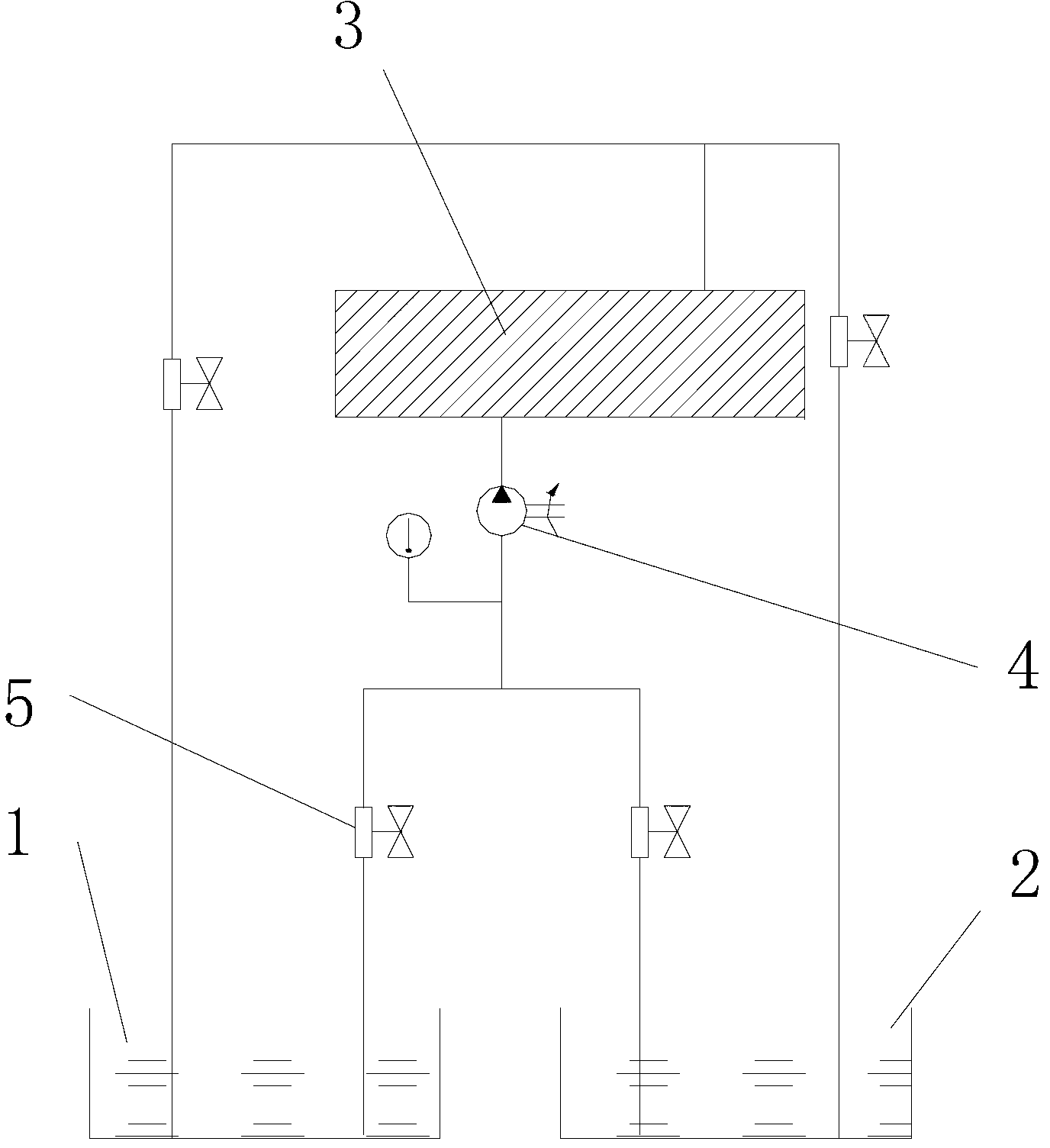
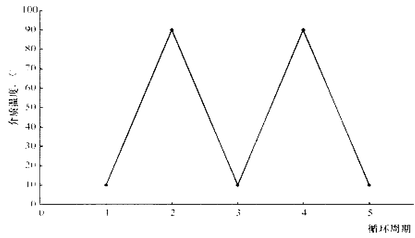
[0004] 1. Since both the high-temperature medium and the low-temperature medium use the same pump 4 to provide circulation power, and the heat exchange between the medium and the pump 4 occurs when the medium passes through the pump, the temperature of the medium injected into the test piece 3 rises and falls relatively gently. The temperature difference is small, and it is impossible to do a severe thermal strain impact test on the product, such as figure 2 shown;
[0005] 2. The thermal cycle test equipment cannot complete thermal cycle and thermal shock tests at temperatures below 0°C and lower;
[0006] Since the vehicle radiator contains components with large differences in thickness, heat storage, and thermal strain, such as fastening water chambers, sealing rings, fins, flat
Method used
View moreImage
Smart ImageViewing Examples

Examples
 PUM
 Abstract
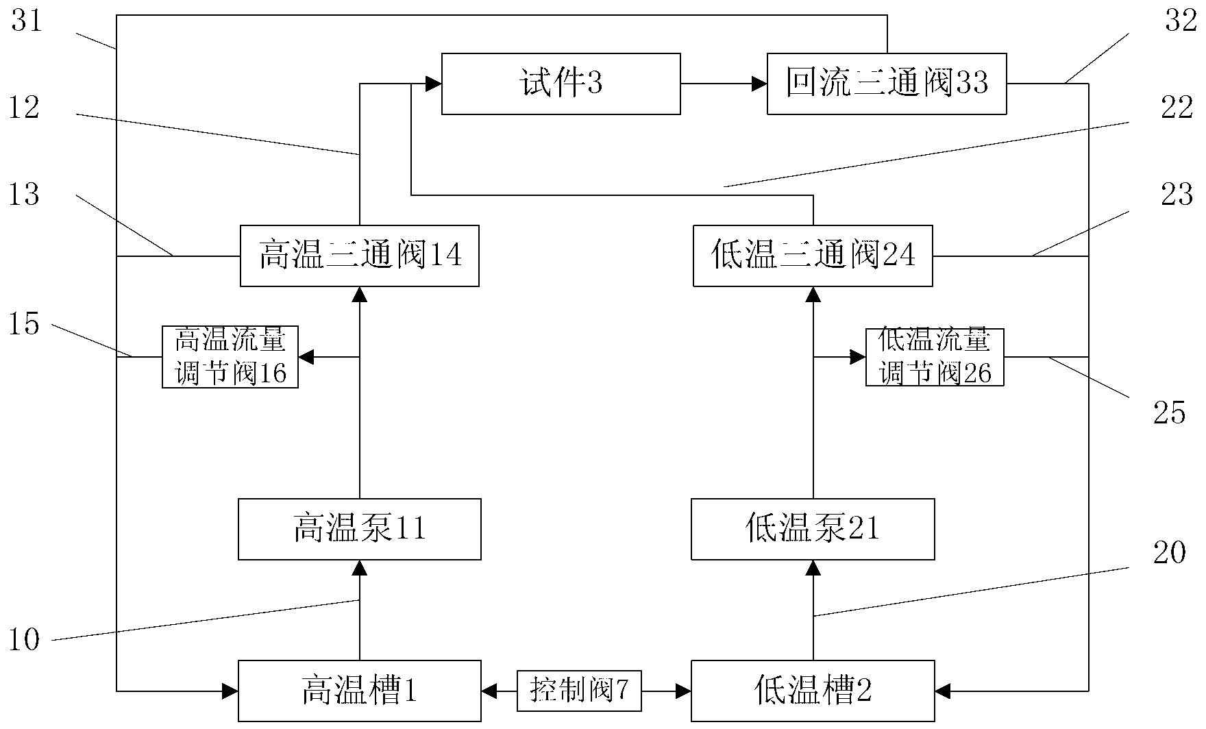
The invention discloses thermal cycle test equipment. The thermal cycle test equipment comprises a high-temperature tank, a low-temperature tank and a circulating pipeline system, wherein the circulating pipeline system comprises a high-temperature medium pipeline connected with the high-temperature tank, a low-temperature medium pipeline connected with the low-temperature tank, and a reflux pipeline used for medium reflux, the high-temperature medium pipeline is provided with a high-temperature pump, a high-temperature connecting pipe is arranged between an outlet of the high-temperature pump and a medium inlet of a test specimen, a high-temperature heat exchange pipe is arranged between the outlet of the high-temperature pump and the high-temperature tank, the low-temperature medium pipeline is provided with a low-temperature pump, a low-temperature connecting pipe is arranged between an outlet of the low-temperature pump and the medium inlet of the test specimen, a low-temperature heat exchange pipe is arranged between the outlet of the high-temperature pump and the low-temperature tank, the reflux pipeline comprises a high-temperature reflux pipeline and a low-temperature reflux pipeline which are arranged in parallel and connected with a medium outlet of the test specimen, the high-temperature reflux pipeline is connected with the high-temperature tank, and the low-temperature reflux pipeline is connected with the low-temperature tank. The invention also discloses a thermal cycle test method. The thermal cycle test equipment and the test method can be used for realizing the rapid change of temperature.
Description
technical field [0001] The invention belongs to the technical field of thermal shock / thermal cycle test, and in particular relates to thermal cycle test equipment and a test method for internal thermal cycle test of a vehicle radiator. Background technique [0002] Such as figure 1 Shown is a structural schematic diagram of an existing heat cycle test equipment. The thermal cycle test equipment includes a high-temperature tank 1, a low-temperature tank 2, and a circulation pipeline arranged between the high-temperature tank 1, the low-temperature tank 2 and the test piece 3. The high-temperature tank 1 and the low-temperature tank 2 are respectively filled with high and low temperature media. In addition, the high-temperature medium and the low-temperature medium are both injected into the test piece 3 through a pump 4. The high-temperature medium pipe and the low-temperature medium pipe are respectively provided with regulating valves 5 for adjusting the flow rate. After p...
Claims
Login to View More Application Information
Patent Timeline
 IPC IPC(8): G01N3/60
Inventor胡昊熊静
OwnerSOUTH AIR INT