Air-flow type drying oven for drying coating layer of radiate material and blast nozzle parts thereof

A technology for air nozzles and components, which is applied in the field of drying ovens and its air nozzle components to achieve the effects of increasing orientation, reducing wind pressure loss, and increasing direct contact area

Active Publication Date: 2009-04-29
CHANGZHOU YONGSHENG NEW MATERIALS EQUIP CO LTD
View PDF4 Cites 13 Cited by
  • Summary
  • Abstract
  • Description
  • Claims
  • Application Information

AI Technical Summary

Problems solved by technology

[0007] The purpose of the present invention is to solve the aforementioned technical problems existing in the air spray nozzles used in the existing drying ovens, and to provide an airflow that can fully heat the radial materials with hot air and has a good drying effect on the coatings on the radial materials during use. Drying box and its tuyere parts

Method used


Image

  • Air-flow type drying oven for drying coating layer of radiate material and blast nozzle parts thereof
  • Air-flow type drying oven for drying coating layer of radiate material and blast nozzle parts thereof
  • Air-flow type drying oven for drying coating layer of radiate material and blast nozzle parts thereof

Examples


Embodiment 1

[0041] (Embodiment 1, air nozzle part)

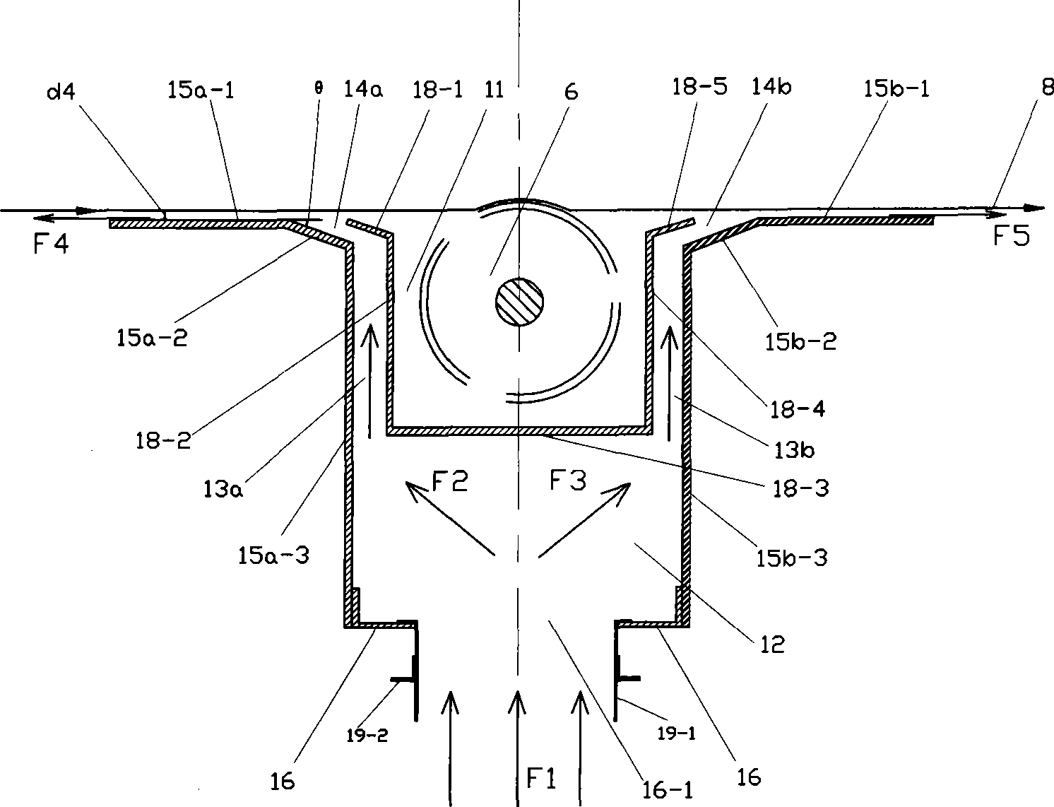
[0042] See figure 1 and figure 2 , the tuyere component in this embodiment is a box 1 . The middle of the upper part of the box body 1 is a guide roller groove 11, and the box body 1 has an inner chamber 12 at the lower part and left air ducts 13a and right air ducts 13b directly connected with the inner chamber 12 at the left and right sides of the upper part. The air outlet of the left air channel 13a is a parallel air flow type left air nozzle 14a inclined to the left, the air outlet of the right air channel 13b is a parallel air flow type right air nozzle 14b inclined to the right, and the box body 1 also has an air inlet located at the lower part .

[0043] The box body 1 includes a left side panel 15 a , a right side panel 15 b , a bottom panel 16 , a front panel 17 a , a rear panel 17 b and a middle panel 18 .

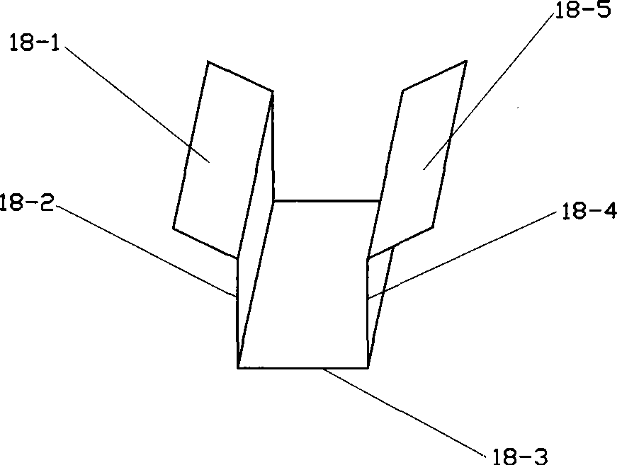
[0044] See figure 2 , the middle plate 18 is a groove-shaped folded plate, and this groove is the guide roller g...

Embodiment 2

[0056] (Embodiment 2, air nozzle parts)

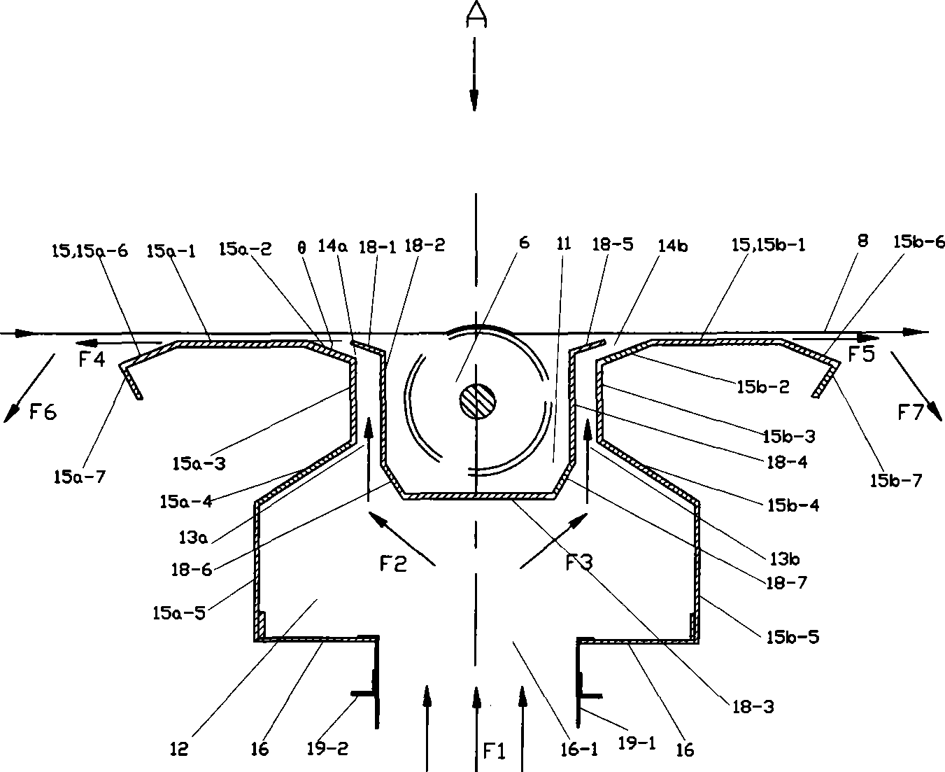
[0057] See image 3 and Figure 4 , the rest of this embodiment is the same as that of Embodiment 1, the difference is that the middle plate includes the following plate sections connected in sequence: the left air nozzle inner slant plate 18-1 inclined upward to the left, the left air duct inner plate 18-2 , the slanted plate 18-6 inside the left air duct inclined downward to the right, the upper side plate 18-3 of the horizontal box body, the inclined plate 18-7 inside the right air duct inclined downward to the left, the inner plate 18-4 of the right air duct and the The right tuyere inboard sloping plate 18-5 of upper right slant.

[0058] The left side plate 15a includes the horizontal support plate 15a-1 of the left air nozzle connected in sequence, the first outer slant plate 15a-2 of the left air nozzle inclined downward to the right, the outer plate 15a-3 of the left air duct, and the left air nozzle inclined downward to the...

Embodiment 3 and Embodiment 4

[0066] (Embodiment 3 and Embodiment 4, air nozzle parts)

[0067] still see image 3 and Figure 4 , Embodiment 3 corresponds to Embodiment 1, and Embodiment 4 corresponds to Embodiment 2. Embodiment 3 is the same as the corresponding embodiment with the rest of embodiment 4, the difference is:

[0068] The left end of the left air nozzle horizontal support plate 15a-1 of the left side plate 15a is also connected with the left air nozzle second outer slant plate 15a-6 inclined downward to the left and the left air nozzle third outer slant plate inclined to the right downward from right to left. Outer ramps 15a-7.

[0069] The right end of the right air nozzle horizontal support plate 15b-1 of the right side plate 15b is also connected with the right air nozzle second outer slant plate 15b-6 inclined downward to the right and the third right air nozzle inclined downward to the left from left to right. Outer sloped plate 15b-7.

[0070] The third outer slant plate 15a-7 of ...


PUM


Abstract

The invention discloses an air flow drying oven for drying the coating of a radiate material and a blast nozzle part thereof. The blast nozzle part is a case, the lower part of which is provided with an air inlet. The middle of the upper part of the case is provided with a guide roller groove, and the case is provided with an inner cavity at the lower part and a left air duct and a right air duct which are positioned at the left side and the right side of the upper part and directly communicated with the inner cavity. An air outlet of the left air duct is a left parallel air flow blast nozzle which inclines towards the left, and the air outlet of the right air duct is a right parallel air flow blast nozzle which inclines towards the right. When the blast nozzle part is used in the drying oven, the left and right blast nozzles accelerate the flow flowing to the left and right sides of the blast nozzle part, and a left horizontal supporting plate and a right horizontal supporting plate lead the air flow to form parallel wind which is parallel to the radiate material, thus increasing the direct contact area between the wind and the radiate material, leading the radiate material surface to be heated evenly and the heat exchange between the parallel hot wind and the radiate material to be more sufficient, improving the heat exchange efficiency and having better drying quality due to even heating.

Description

technical field [0001] The invention relates to a drying device, in particular to a drying box for drying a liquid coating coated on one side surface of a web-like material and an air nozzle part thereof. Background technique [0002] Radial materials refer to thinner banner-shaped paper, plastic film, non-woven fabrics, etc. In order to increase the functions of these radial materials, it is often necessary to coat one side of these web-shaped materials with a liquid coating with certain functions. Layers, such as adhesives, anti-adhesive silicone oil or protective coatings, are then dried by a drying process to fix the liquid coating on the radial material. The drying of the liquid coating on the radial material is usually carried out in a drying tunnel or drying oven provided with a radial material inlet and outlet and a radial material conveying device. The box body of the drying box is generally made of thermal insulation materials; some drying boxes are also equipped ...

Claims


Application Information

Patent Timeline
Patent Type & Authority Applications(China)
IPC IPC(8): B05D3/04B05B1/14
Inventor 黄晓
Owner CHANGZHOU YONGSHENG NEW MATERIALS EQUIP CO LTD
Why Eureka
Try Eureka