Vertical rotary heating furnace of main shaft steel ingot for wind driven generator

A wind-driven generator and rotary heating technology, which is applied to heat treatment furnaces, furnaces, furnace types, etc., can solve the problems of uneven heating of the steel ingot of the main shaft of the wind-driven generator, affect the uniformity of heating, and increase the holding time, so as to improve labor efficiency, The effect of shortening the heating time and increasing the heating rate

Active Publication Date: 2012-09-19
SHANDONG LAIWU JINLEI WIND POWER TECH
View PDF0 Cites 0 Cited by
  • Summary
  • Abstract
  • Description
  • Claims
  • Application Information

AI Technical Summary

Problems solved by technology

Apparently, the disadvantages of heating the wind turbine main shaft steel ingot with this large-scale heating furnace are: 1. Since the wind turbine main shaft steel ingot is motionless, and the direction of the gas burner is fixed, so, 2. In order to overcome the shortcoming of uneven heating, the method currently adopted is: in different temperature periods, increase the holding time, such as when the wind turbine spindle steel ingot at room temperature is packed When entering the heating furnace at 620°C-650°C, it needs to be kept warm for 8-12 hours, and then heated at a rate of 50-70°C per hour to 830-860°C, kept for 10-18 hours, and then heated to Only when the forging temperature is 1200-1240 ℃ can it be out of the furnace, so that the holding time is increased and the labor efficiency is reduced; 3. Due to the use of two steel pads, these two steel pads are basically oxidized during the heating process, so that The steel ingot of the main shaft of the wind turbine in the hot state is close to the bottom of the furnace, which not only affects the uniformity of heating in the later stage, but also causes waste of steel

Method used


Image

  • Vertical rotary heating furnace of main shaft steel ingot for wind driven generator
  • Vertical rotary heating furnace of main shaft steel ingot for wind driven generator
  • Vertical rotary heating furnace of main shaft steel ingot for wind driven generator

Examples


Embodiment 1

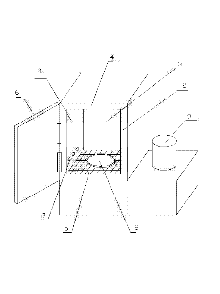
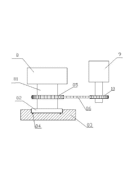
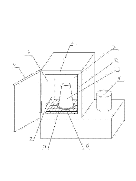
[0014] figure 1 , figure 2 , image 3 An example is given, and it was put into trial operation in our company in January 2011. Such as figure 1 , figure 2 , image 3 As shown, the wind turbine main shaft steel ingot vertical rotary heating furnace includes a left furnace wall 1, a right furnace wall 2, a rear furnace wall 3, a top furnace wall 4, a furnace bottom 5 and a furnace door 6. There is an insulation layer, the furnace bottom 5 is a refractory brick layer, and a gas burner 7 is provided at the lower part of the left furnace wall 1 and the right furnace wall 2. Turntable 8, the internal length of left furnace wall 1, right furnace wall 2 is 350cm, and internal height is 450cm, and the internal height of back furnace wall 3 is 450cm, and internal width is 350cm, and when wind power generator main shaft steel ingot 11 is heated, wind force The main shaft steel ingot 11 of the generator faces down and stands on the circular turntable 8. The rotation of the circula...

Embodiment 2

[0020] The structure of the vertical rotary heating furnace for the main shaft steel ingot of the wind power generator is the same as that in Embodiment 1. When heating the wind turbine main shaft steel ingot, put it into a heating furnace at 650°C from room temperature, keep it warm for 3 hours, then heat it at a rate of 70°C per hour, raise the temperature to 860°C, keep it warm for 4 hours, and then raise the temperature to 1240°C, using a matching special forklift to take out the furnace.

[0021] Compared with the existing heating furnace, when heating a steel ingot for the main shaft of a wind turbine, the two holding times are shortened by an average of 7 hours and 10 hours respectively, and the total time for completing a furnace is shortened by an average of 17 hours. And the heated wind turbine main shaft steel ingot is suitable for forging requirements.

Embodiment 3

[0023] The structure of the vertical rotary heating furnace for the main shaft steel ingot of the wind power generator is the same as that in Embodiment 1. When heating the wind turbine main shaft steel ingot, put it into a heating furnace at 620°C from room temperature, keep it warm for 3 hours, then heat it at a rate of 80°C per hour, raise the temperature to 830°C, keep it warm for 7 hours, and then raise the temperature to 1200 ℃, using a matching special forklift for the furnace.

[0024] Compared with the existing heating furnace, when heating a steel ingot for the main shaft of a wind turbine, the holding time of the two stages is shortened by 7 hours on average, and the total time for completing one furnace is shortened by 14 hours on average. And the heated wind turbine main shaft steel ingot is suitable for forging requirements.


PUM

PropertyMeasurementUnit
diameteraaaaaaaaaa
diameteraaaaaaaaaa
diameteraaaaaaaaaa

Abstract

The invention discloses a vertical rotary heating furnace of a main shaft steel ingot for a wind driven generator. The heating furnace comprises a left furnace wall, a right furnace wall, a rear furnace wall, a top furnace wall, a furnace bottom and a furnace door, wherein an insulating layer is arranged on the inner layer of the furnace wall; a refractory brick layer is arranged at the furnace bottom; and gas burner nozzles are arranged on the lower parts of the left furnace wall and the right furnace wall. The furnace is characterized in that: a circular rotary disc made of refractory materials is arranged in the middle of the furnace bottom; the internal length of the left and right furnace walls is 350 cm, and the internal height is 450 cm; and the internal height of the rear furnace wall is 450 cm, and the internal width is 350 cm. When the furnace is used, the large head of the main shaft steel ingot of the wind driven generator is arranged downwards and the main shaft steel ingot is erected on the circular rotary disc. In the vertical rotary heating furnace of the main shaft steel ingot for the wind driven generator, the main shaft steel ingot of the wind driven generator is heated while vertically rotating, so that the surface of the main shaft steel ingot is heated uniformly; therefore, temperature preservation time can be shortened, the increase of the temperature rising speed and the improvement of the labor efficiency can be facilitated, energy consumption is reduced, production cost is reduced, and steel is saved.

Description

technical field [0001] The invention relates to an improvement of a heating furnace for a large steel ingot, in particular to a vertical rotation heating of a wind power generator main shaft steel ingot which can make a large steel ingot heat and rotate vertically in the heating furnace, thereby improving the uniformity of heating furnace. Background technique [0002] In the production of the wind turbine main shaft, the raw materials used are large steel ingots in the shape of a truncated cone or a truncated pyramid, with a diameter of 85-123.1 cm at the bottom, a diameter of 107-129.8 cm at the top, and a length of 201-201.8 cm. 13-27 tons. Before forging, it needs to be heated by a large heating furnace to reach the required forging temperature. This large heating furnace includes the left furnace wall, right furnace wall, rear furnace wall, top furnace wall, furnace bottom and furnace door. The inner layer is equipped with insulation layer, the bottom of the furnace i...

Claims


Application Information

Patent Timeline
Patent Type & Authority Patents(China)
IPC IPC(8): C21D9/70
Inventor 伊廷雷李新生
Owner SHANDONG LAIWU JINLEI WIND POWER TECH
Why Eureka
Try Eureka