
A high-efficiency curing device for glass fiber reinforced plastic casing production

A technology of FRP casing and curing device, which is applied in the field of FRP casing production and molding, which can solve the problems of easy damage, affecting the pass rate of molding, and affecting the pass rate of curing molding, etc., and achieve the effect of uniform heating, improving efficiency and pass rate

Active Publication Date: 2021-11-12
江苏金安电气有限公司
View PDF0 Cites 0 Cited by
  • Summary
  • Abstract
  • Description
  • Claims
  • Application Information

AI Technical Summary

Problems solved by technology

[0002] FRP dry-type transformer bushings are devices for one or several conductors to pass through partitions such as walls or boxes for insulation and support. There are gas-impregnated bushings, oil-impregnated paper bushings, adhesive paper bushings, glue Paper-impregnated sleeves, rubber-impregnated fiber sleeves, etc., the rubber-impregnated fibers are made of resin-impregnated fiber rolls for main insulation. During the production and molding process of FRP sleeves, multiple anti-corrosion bellows need to be arranged on the surface. In order to improve the anti-corrosion performance of the FRP casing after molding, it is necessary to use a curing molding device to improve the curing effect and improve the molding efficiency. The inside cannot be rotated, which causes the surface to be heated unevenly during the curing molding process, which affects the molding pass rate, and its clamping effect on the sleeve before curing molding is not good enough, which is prone to occur during the curing molding process. Damage and other conditions will further affect the pass rate of curing molding

Method used


Image

  • A high-efficiency curing device for glass fiber reinforced plastic casing production
  • A high-efficiency curing device for glass fiber reinforced plastic casing production
  • A high-efficiency curing device for glass fiber reinforced plastic casing production

Examples


Embodiment 1

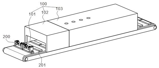
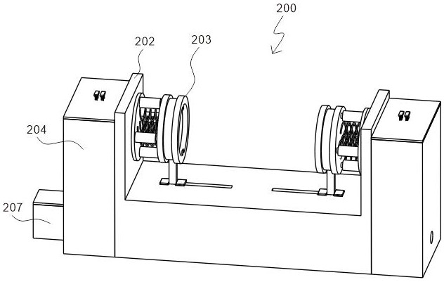
[0034] refer to figure 1 with figure 2 , is the first embodiment of the present invention, and this embodiment provides a kind of high-efficiency FRP casing production curing device, and the high-efficiency FRP casing production curing device includes a curing molding unit 100 and a clamping unit 200, and the FRP casing is solidified During the forming process, it is clamped and rotated by the clamping unit 200, so that the surface is heated more uniformly, thereby improving the efficiency and pass rate of curing and forming.

[0035] Specifically, the curing molding unit 100 includes a conveyor belt 101, a preform curing box 102 arranged on the top of the conveyor belt 101, and a deep forming curing box 103 arranged on the top of the conveyor belt 101 and on the right side of the preform curing box 102, through The conveyor belt 101 transports the FRP casing to be cured to the interior of the preformed curing box 102 and the deep forming curing box 103, pre-cures it through...

Embodiment 2

[0039] refer to Figure 2~9 , is the second embodiment of the present invention, which is based on the previous embodiment.

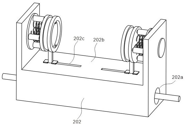
[0040] Specifically, the connection assembly 202 includes a through hole 202a disposed inside, a clamping cavity 202b disposed on the top, and a moving groove 202c disposed on the inner wall of the clamping cavity 202b. The casing is clamped and fixed to prevent it from shifting during the curing and molding process, which will affect the efficiency of curing and molding.

[0041] Preferably, the clamping assembly 203 includes a connecting plate 203a disposed inside the clamping cavity 202b, a clamping frame 203b disposed on one side of the connecting plate 203a, and a telescopic guide 203c disposed between the connecting plate 203a and the clamping frame 203b , the compression spring 203d arranged on one side of the connecting plate 203a, and the connecting rod 203e arranged on the other side of the connecting plate 203a, one end of the connecting rod...

Embodiment 3

[0047] refer to Figure 8~12 , is the third embodiment of the present invention, which is based on the first two embodiments.

[0048] Specifically, the moving part 205f includes a moving ring 205f-a, a fixed plate 205f-b arranged on the top of the moving ring 205f-a, an movable rod 205f-c arranged in the middle of the protective top cover 204b, and a movable rod 205f-c arranged on the top of the movable rod 205f-c. The pressing block 205f-d, the second tension spring 205f-e arranged at the bottom of the pressing block 205f-d, the limit frame 205f-f arranged at the bottom end of the movable rod 205f-c, the side of the moving ring 205f-a and The third tension spring 205f-g matched with the connecting plate 205b, and the limit rod 205f-h arranged on the side of the fixed rod 205d, the moving ring 205f-a includes a limiter arranged on the side and matched with the limit rod 205f-h. The position slot M, the fixed plate 205f-b includes a chute N arranged on the top and matched wit...


PUM


Abstract

The invention discloses a high-efficiency curing device for the production of FRP sleeves, which includes a curing molding unit, including a conveyor belt, a preformed curing box arranged on the top of the conveyor belt, and a preform curing box arranged on the top of the conveyor belt and located at the preform The deep forming and curing box on the right side of the forming and curing box; the clamping unit is arranged on the surface of the conveyor belt, including a placing plate, a connecting component arranged on the top of the placing plate, and a clamping component arranged inside the connecting component . The protective components arranged on both sides of the connecting component. When the present invention is in use, the casing curing and forming unit performs curing and molding operations on the FRP casing, and at this time, the FRP casing is clamped through the cooperative use of the driving assembly, the first transmission assembly, the second transmission assembly, and the clamping assembly At the same time, it is rotated during the curing and forming process, so that the surface of the FRP casing is heated more uniformly, and the efficiency and pass rate of curing and forming are improved.

Description

technical field [0001] The invention relates to the technical field of production and molding of FRP sleeves, in particular to a curing device for high-efficiency FRP sleeve production. Background technique [0002] FRP dry-type transformer bushings are devices for one or several conductors to pass through partitions such as walls or boxes for insulation and support. There are gas-impregnated bushings, oil-impregnated paper bushings, adhesive paper bushings, glue Paper-impregnated sleeves, rubber-impregnated fiber sleeves, etc., the rubber-impregnated fibers are made of resin-impregnated fiber rolls for main insulation. During the production and molding process of FRP sleeves, multiple anti-corrosion bellows need to be arranged on the surface. In order to improve the anti-corrosion performance of the FRP casing after molding, it is necessary to use a curing molding device to improve the curing effect and improve the molding efficiency. The inside cannot be rotated, which ca...

Claims


Application Information

Patent Timeline
Patent Type & Authority Patents(China)
IPC IPC(8): B29C35/00B29C35/02
CPCB29C35/002B29C35/02
Inventor 安泽庆张艺潇
Owner 江苏金安电气有限公司
Learn More