Error calibration compensation method of accelerometers in MEMS-IMU under dynamic environment

An accelerometer and compensation method technology, which is applied in the testing/calibration of speed/acceleration/shock measurement equipment, speed/acceleration/shock measurement, measurement devices, etc., and can solve problems such as unsatisfactory error compensation results

Active Publication Date: 2013-09-25
SOUTHEAST UNIV
View PDF3 Cites 15 Cited by
  • Summary
  • Abstract
  • Description
  • Claims
  • Application Information

AI Technical Summary

Problems solved by technology

[0004] Usually, the installation error and scaling factor method of calibrating the accelerometer is carried out under static or quasi-static conditions,

Method used


Image

  • Error calibration compensation method of accelerometers in MEMS-IMU under dynamic environment
  • Error calibration compensation method of accelerometers in MEMS-IMU under dynamic environment
  • Error calibration compensation method of accelerometers in MEMS-IMU under dynamic environment

Examples


Embodiment Construction

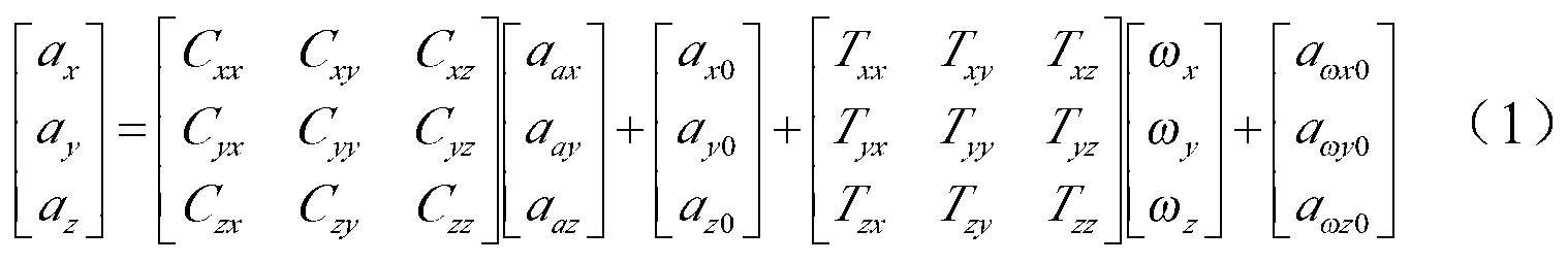
[0020] specific implementation plan

[0021] Introduce detailed implementation scheme and steps of the present invention in conjunction with accompanying drawing:

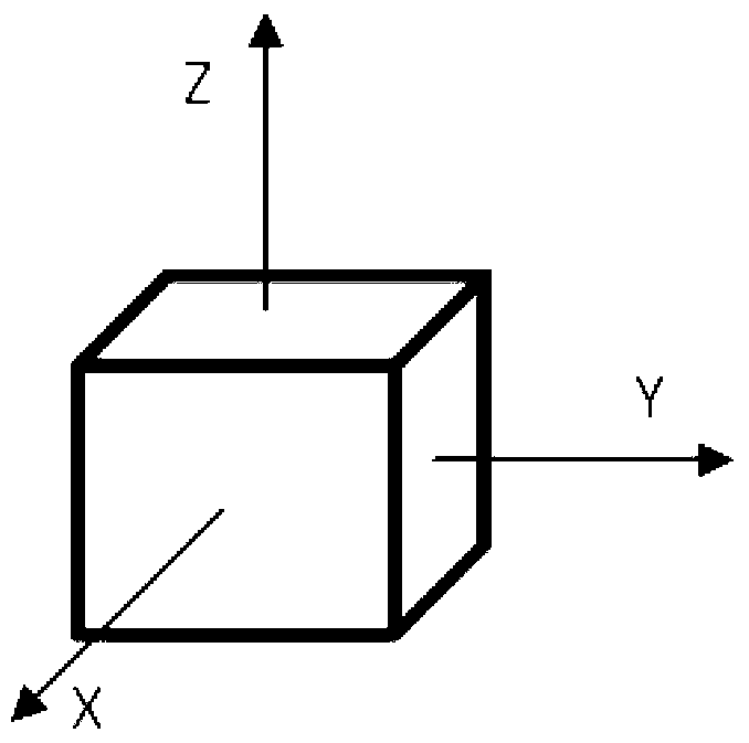
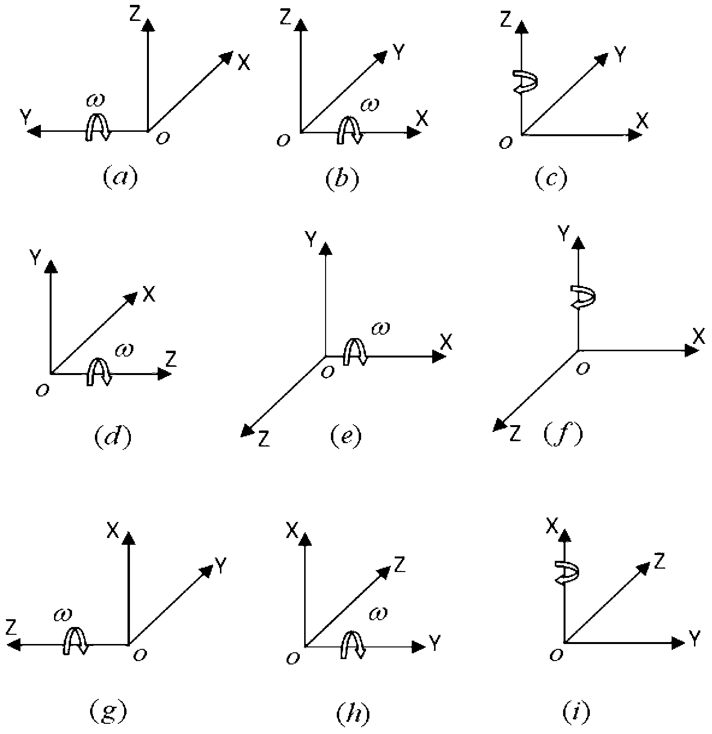
[0022] will be like figure 1 The three-axis accelerometer shown is installed on the base of the two-axis turntable. The sensitive axes of the Z accelerometer and X accelerometer point to the outer frame and the inner frame of the turntable respectively. The outer frame of the turntable points to the sky, and the inner frame points to the north direction. The sensitive axis of the meter automatically points to the west, such as figure 2 - Shown in (a).

[0023] After the IMU warms up for a period of time, fix the inner frame of the turntable, and set the outer frame of the turntable to run in rate mode, the rate is ω. At this time, the sensitive dynamic acceleration of the Z accelerometer is a=g cos(ωt), where g is the local earth Acceleration of gravity, t is the running time of the turntable, synchronously col...


PUM


Abstract

The invention discloses an error calibration compensation method of three axial accelerometers in an MEMS-IMU under the dynamic environment. The error calibration compensation method includes the steps of enabling an outer frame of a rotary table to operate in a speed mode, then enabling the Z axis to return to the zero position, enabling an inner frame of the rotary table to operate in a sine mode, changing installation of the IMU, respectively enabling the direction of a sensitive shaft of the X-axis accelerometer and the direction of a sensitive shaft of the Y-axis accelerometer to be parallel to the sky direction, enabling the accelerometers to sense the dynamic accelerated speeds and the dynamic angle speeds in the operating mode same as that of the Z-axis accelerometer, recording the output data of the three axial accelerometers, carrying out analysis and processing, and obtaining the installing errors, the calibration coefficients and the zero wanders of the three axial accelerometers in the MEMS-IMU and influence factors of the dynamic angle speeds on the accelerometers. The error calibration compensation method is simple and easy to implement, obviously improves the accuracy of an MEMS-IMU system, and is particularly suitable for systems with low-cost and low-accuracy MEMS accelerometers.

Description

technical field [0001] The invention provides an error calibration and compensation method for the accelerometer in the MEMS-IMU under the dynamic environment, which can be used for the error calibration and compensation of the three-axis accelerometer in the MEMS-IMU, and is especially suitable for the inertia of the low-cost micro-electromechanical accelerometer. unit of measurement. Background technique [0002] MEMS (Micro-Electro-MechanicalSystems, MEMS) micro-inertial measurement unit is generally composed of a gyroscope and an accelerometer. Inertial measurement brings new opportunities for change and development. [0003] The micro inertial measurement unit is the core sensor of the entire inertial measurement system, which determines the performance and measurement accuracy of the entire system. As one of the two core components, the accelerometer is not very accurate, so it is particularly important to analyze and calibrate its main errors. [0004] Usually, the...

Claims


Application Information

Patent Timeline
IPC IPC(8): G01P21/00
Inventor 陈熙源刘虎黄浩乾周智恺汤传业
Owner SOUTHEAST UNIV
Why Eureka
Try Eureka