Rotation limitation and orientation identification mechanism and limiting and identifying method thereof

A direction recognition and rotation limit technology, which is applied in the direction of devices, mechanical control devices, and instruments that prevent/restrict/restore the movement of parts of the control mechanism, and can solve problems such as damage, complicated limit devices, and inconvenient use. To achieve the effect of simple use and clever design

Active Publication Date: 2013-09-25
CHANGZHOU MINGSEAL ROBOT TECH CO LTD
View PDF7 Cites 11 Cited by
  • Summary
  • Abstract
  • Description
  • Claims
  • Application Information

AI Technical Summary

Problems solved by technology

[0003] When there is no rotation limit and direction identification mechanism, if misoperation occurs, the air pipe and rubber hose at the end of the rotating shaft will be wound beyond the winding limit, which may damage the components installed on the shaft end of the rotating mechanism and the components to be processed; if the work is completed If the reset is not performed correctly or the emergency stop is performed in case of an emergency, after the machine is powered on again, the rotation direction of the resetting shaft cannot be recognized, resulting in the machine moving in the opposite direction to the actual reset direction, which will cause the air pipe and rubber hose at the end of the rotating shaft to be entangled Exceeding

Method used


Image

  • Rotation limitation and orientation identification mechanism and limiting and identifying method thereof
  • Rotation limitation and orientation identification mechanism and limiting and identifying method thereof

Examples


Embodiment 1)

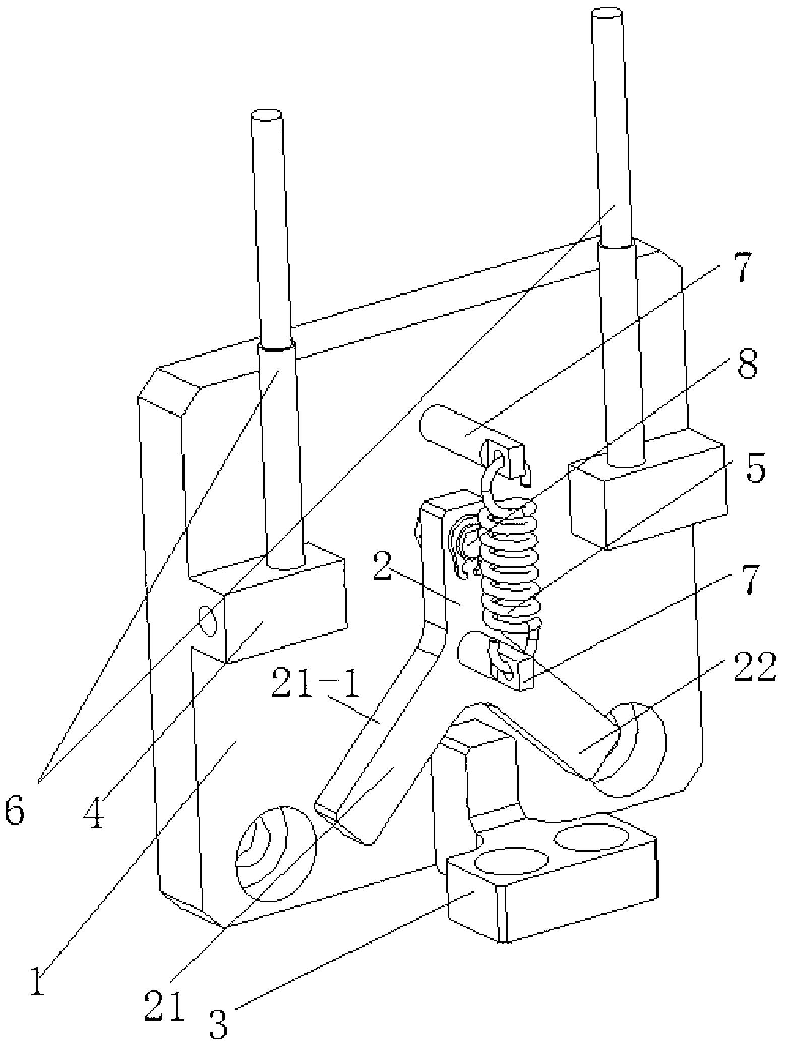
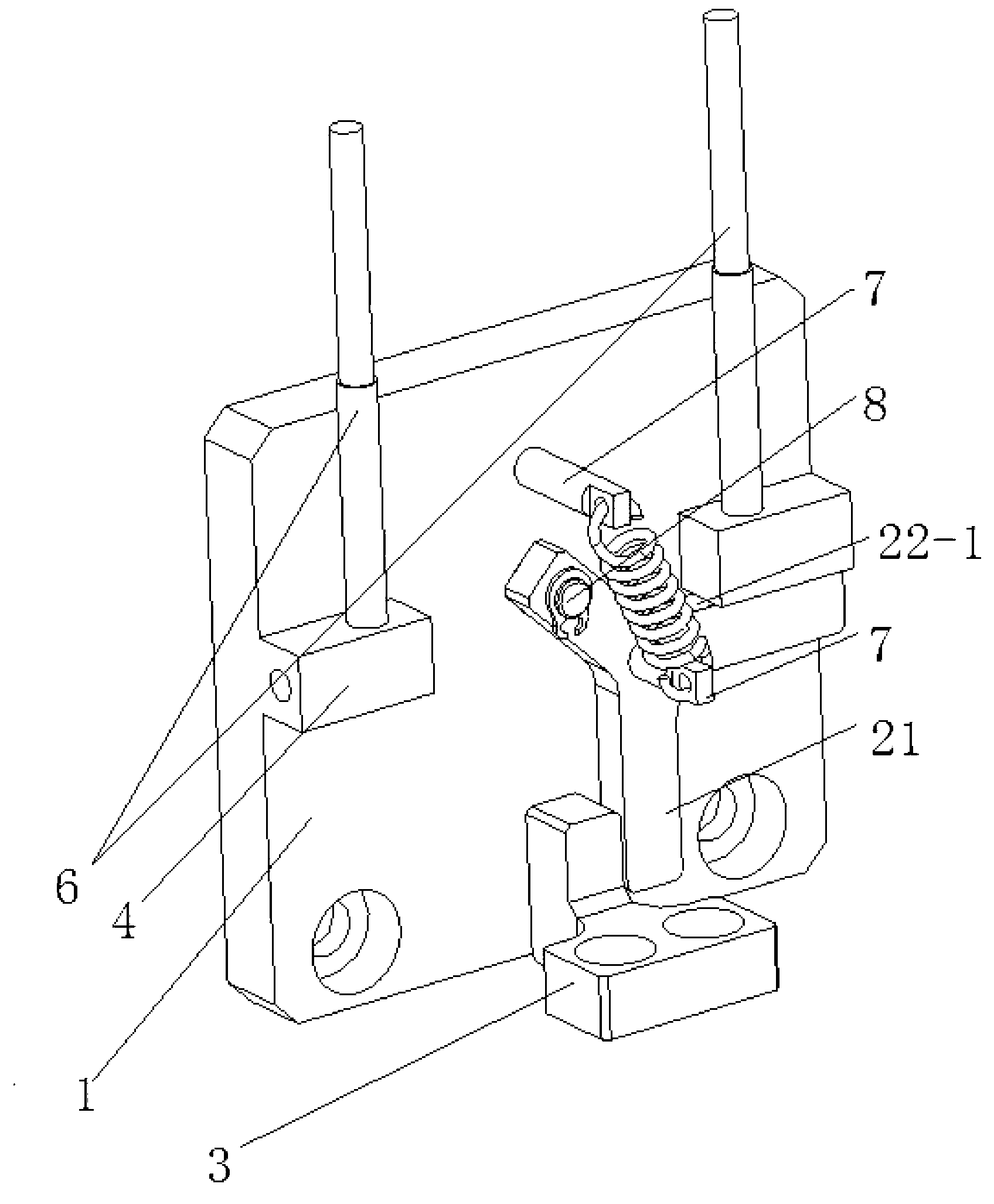
[0021] See figure 1 with figure 2 , a rotation limit and direction identification mechanism of this embodiment, including a base plate 1, a rotation plate 2, a striker 3, two stoppers 4, elastic members 5, two direction identification elements 6, and two elastic member hook columns 7 and reel 8. Elastic member 5 adopts extension spring, certainly also can be other objects that can provide upward pulling force for rotating wrench 2, such as rubber band and the like.

[0022] See figure 1 , the rotating plate 2 in this embodiment is in an inverted "Y" shape, the upper end is connected to the bottom plate 1 through the rotating shaft 8, and the lower end includes a left limiting plate 21 and a right limiting plate 22 that are connected at one end and form an included angle at the other end, The angle between the left limiting side 21 - 1 and the right limiting side 22 - 1 on the outside of the left limiting plate 21 and the right limiting plate 22 is 90°.

[0023] The strike...


PUM


Abstract

The invention discloses a rotation limitation and orientation identification mechanism and a limiting and identifying method of the rotation limitation and orientation identification mechanism. The rotation limitation and orientation identification mechanism comprises a bottom plate, a rotating plate, a rammer, two stop blocks and an elastic piece. The upper end of the rotating plate is connected with the bottom plate in a rotating mode. The lower end of the rotating plate is provided with a left limiting plate and a right limiting plate, wherein one end of the left limiting plate and one end of the right limiting plate are connected, and an included angle is formed between the other end of the left limiting plate and the other end of the right limiting plate. The included angle between the limiting edge located on the outer side of the left limiting plate and the limiting edge located on the outer side of the right limiting plate is 90 degrees. The rammer is connected with a rotating shaft and is driven by the rotating shaft to rotate. The rammer and the bottom plate are located on two planes respectively, and the two planes are perpendicular to each other. The starting position of the rammer is in the middle of the included angle formed between the left limiting plate and the right limiting plate of the rotating plate. The rammer can make contact with the left limiting plate or the right limiting plate in the rotating process. The two stop blocks are fixed on the bottom plate, located on two sides of the rotating plate, and matched with the limiting edges respectively to restrict the rotating amplitude of the left limiting plate and the rotating amplitude of the right limiting plate. The elastic piece provides upward tensile force for the rotating plate. The rotation limitation and orientation identification mechanism can be used for limiting a rotating mechanism or the rotating shaft by +/-360 degrees, and is ingenious in design and simple to use.

Description

technical field [0001] The invention relates to a rotation limiting and direction identifying mechanism and a limiting and identifying method thereof. Background technique [0002] In many mechanical equipment, there will be a rotating shaft, and its rotating position or the rotating stroke needs to be controlled. Generally speaking, due to the influence of the gas circuit and electric wires, the rotation of the rotating shaft needs to be controlled within the range of ±360°, so A limit device and a shaft direction recognition device are required. [0003] When there is no rotation limit and direction identification mechanism, if misoperation occurs, the air pipe and rubber hose at the end of the rotating shaft will be wound beyond the winding limit, which may damage the components installed on the shaft end of the rotating mechanism and the components to be processed; if the work is completed If the reset is not performed correctly or the emergency stop is performed in cas...

Claims


Application Information

Patent Timeline
IPC IPC(8): G05G5/00
Inventor 曲东升闵继江刘彦武李长峰
Owner CHANGZHOU MINGSEAL ROBOT TECH CO LTD
Why Eureka
Try Eureka