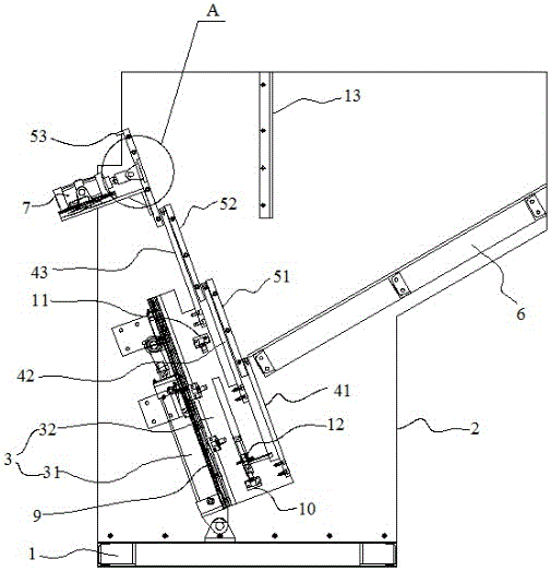
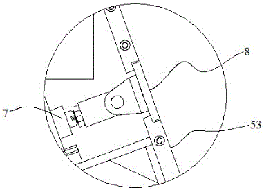
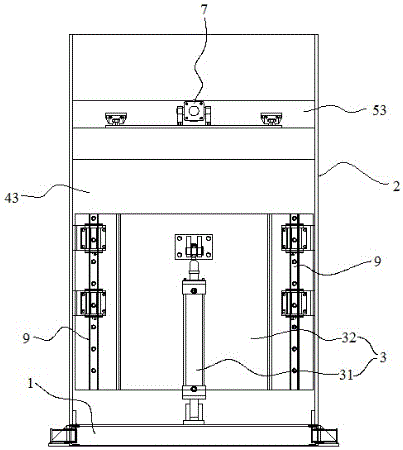
Short-section bar feeding mechanism

A bar and short joint technology, applied in the field of short joint bar feeding mechanism, can solve the problems of time-consuming, disorderly placement, and cost increase

Active Publication Date: 2016-10-12
西安博大感应科技有限公司
View PDF13 Cites 0 Cited by
  • Summary
  • Abstract
  • Description
  • Claims
  • Application Information

AI Technical Summary

Problems solved by technology

[0002] Bar stock is a material with a certain length of circular or polygonal long rod shape. It is generally the raw material of forgings. It is mostly stretched, or extruded through a mold, and can also be machined. In the production process, it usually needs The feeding device for conveying bar stock. The existing bar stock feeding device usually adopts a transmission mechanism such as a conveyor belt. However,

Method used


Image

  • Short-section bar feeding mechanism
  • Short-section bar feeding mechanism
  • Short-section bar feeding mechanism

Examples


Embodiment Construction

[0022] In describing the present invention, it is to be understood that the terms "center", "upper", "lower", "front", "rear", "left", "right", "vertical", "horizontal", The orientations or positional relationships indicated by "top", "bottom", "inner", "outer", etc. are based on the orientations or positional relationships shown in the drawings, and are only for the convenience of describing the present invention and simplifying the description, rather than indicating or implying References to devices or elements must have a particular orientation, be constructed, and operate in a particular orientation and therefore should not be construed as limiting the invention.

[0023] The terms "first", "second", and "third" are used for descriptive purposes only, and should not be understood as indicating or implying relative importance or implicitly specifying the number of indicated technical features. Thus, features defined as "first", "second" and "third" may explicitly or implic...


PUM


Abstract

The invention discloses a short-section bar feeding mechanism. The mechanism comprises a base, a rack, a driving device, a pushing plate assembly, a fixed plate assembly and a feeding plate arranged in an inclined manner, wherein the rack, the driving device, the pushing plate assembly and the fixed plate assembly are located on the base; and the driving device is fixed to the base, the driving device and the feeding plate are located on the two sides of the pushing plate assembly, and the driving device is used for pushing the pushing plate assembly to move in a reciprocating manner between the first position and the second position. According to the short-section bar feeding mechanism, short-section bars can be conveyed in a unified posture, and the feeding efficiency is improved.

Description

technical field [0001] The invention relates to the technical field of feeding devices, in particular to a short section bar feeding mechanism. Background technique [0002] Bar stock is a material with a certain length of circular or polygonal long rod shape. It is generally the raw material of forgings. It is mostly stretched, or extruded through a mold, and can also be machined. In the production process, it usually needs The feeding device for conveying bar stock. The existing bar stock feeding device usually adopts a transmission mechanism such as a conveyor belt. However, during the conveying process, bars, especially short-section bars, will appear to cross horizontally and vertically and be placed out of order. , is not conducive to the processing of the next process. It is necessary to adjust the posture of the bar material manually or through other devices, which is time-consuming and laborious, which increases the cost and lowers the production efficiency. materi...

Claims


Application Information

Patent Timeline
IPC IPC(8): B23Q7/00B65G47/82
CPCB23Q7/00B65G47/82B65G2201/0217
Inventor 丁美亮刘思哲贺凯
Owner 西安博大感应科技有限公司
Why Eureka
Try Eureka