Nondestructive inspection equipment of casting

A non-destructive flaw detection and casting technology, applied in measuring devices, instruments, scientific instruments, etc., can solve the problem of inability to detect flaws in ultra-thick castings, and achieve the effects of stable and smooth movement, stable connection, and improved accuracy

Active Publication Date: 2012-07-11
NUCLEAR POWER INSTITUTE OF CHINA
View PDF6 Cites 3 Cited by
  • Summary
  • Abstract
  • Description
  • Claims
  • Application Information

AI Technical Summary

Problems solved by technology

[0006] The present invention needs to solve the technical problem that the existing casting flaw detection device cannot detect flaws of ultra-thick castings

Method used


Image

  • Nondestructive inspection equipment of casting
  • Nondestructive inspection equipment of casting
  • Nondestructive inspection equipment of casting

Examples


Embodiment 1

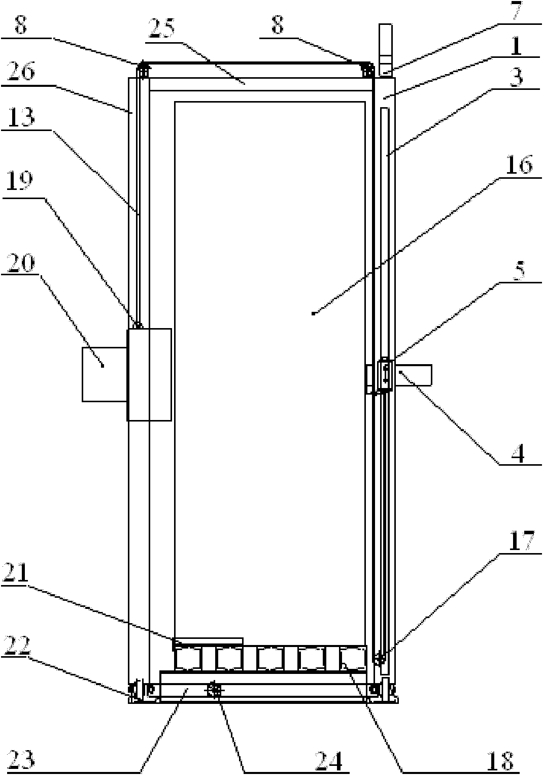
[0032] Such as figure 1 As shown, a non-destructive testing equipment for castings in this embodiment includes a gantry assembly, a Y-direction lifting assembly, a radiation receiving assembly 4, a source assembly 20, a pulley assembly, a chassis assembly and an X-direction moving assembly. Wherein, the gantry assembly includes the gantry right frame 1 and the gantry left frame 26, and the described source assembly 20 and the ray receiving assembly 4 are installed on the gantry right frame 1 and the gantry left frame 26 respectively, on the gantry right frame 1 and the gantry left frame 26 of the gantry assembly. A pulley assembly is installed on the left frame 26 of the gantry, and an X-direction moving assembly for horizontally moving the gantry assembly is installed below the gantry assembly.

[0033]The gantry assembly is the main supporting structure of the equipment of the present invention to provide support for the application source assembly 20 and the ray receiving a...

Embodiment 2

[0052] The difference between this embodiment and embodiment 1 is:

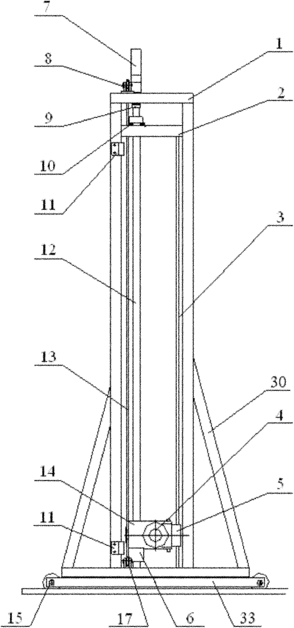
[0053] The Y-direction lifting assembly also includes a Y-direction movement mechanical limiter 2 and a thrust ball bearing 10. The Y-direction movement mechanical limiter 2 is a flat plate in the horizontal direction, which is fixed between the two vertical bars of the right frame 1 of the gantry , the lower surface is in contact with the upper surface of the Y-direction guide rail, and the Y-direction screw runs through the Y-direction movement mechanical limiter 2; the thrust ball bearing 10 is set on the Y-direction screw rod 12, and its upper surface is connected to the Y-direction shaft coupling 9 The lower surface is in contact with the upper surface of the Y-direction movement mechanical limiter 2.

[0054] The Y-direction movement mechanical limit device 2 can prevent the moving element from exceeding the capacity range after the equipment breaks down, and protects the device of the present invention...

Embodiment 3

[0056] The difference between this embodiment and the above two embodiments is:

[0057] The Y-direction lifting assembly also includes a set of Y-direction electronic limiters 11, which are respectively installed on the upper and lower ends of the vertical bar provided with the Y-direction screw on the right frame 1 of the gantry. The distance between the two is determined according to the height of the flaw-detected casting 16.

[0058] Similar to the Y-direction movement mechanical limit device 2, the Y-direction electronic limit device 11 limits the vertical travel range of the source assembly 20 and the radiation receiving assembly 4, and can be flexibly adjusted according to the size of the flaw-detected casting 16, The applicability of the device of the present invention to the flaw-detected castings 16 of different sizes is enhanced; in addition, the use of the Y-direction electronic limit device 11 can realize the limit function without contacting the hoop assembly 14 ...


PUM

PropertyMeasurementUnit
thicknessaaaaaaaaaa
sizeaaaaaaaaaa
thicknessaaaaaaaaaa

Abstract

The invention belongs to the technical field of industrial nondestructive inspection, and more particularly relates to nondestructive inspection equipment of a casting. The nondestructive inspect equipment comprises a gantry assembly, a Y-direction lifting assembly, a probe shielding assembly, a source application assembly, pulley assemblies, an underframe assembly and an X-direction moving assembly, wherein the gantry assembly comprises a right gantry frame and a left gantry frame; the source application assembly and a ray receiving assembly are respectively arranged on the right gantry frame and the left gantry frame; the pulley assemblies are respectively arranged on the right gantry assembly and the left gantry assembly of the gantry assembly; the X-direction moving assembly which is used for horizontally moving the gantry assembly is arranged below the gantry assembly; and the underframe assembly is erected above the X-direction moving assembly and used for supporting a casting subjected to flaw detection. The nondestructive inspection equipment disclosed by the invention solves the technical problem that the ultra-thick casting cannot subjected to flaw detection and achieves the technical effect of carrying out nondestructive flaw detection on the ultra-thick casting.

Description

technical field [0001] The invention belongs to the technical field of industrial nondestructive testing, and in particular relates to nondestructive testing equipment for castings. Background technique [0002] Casting flaw detection is a very important process in industrial production, especially in the manufacture of nuclear engineering equipment. In nuclear engineering construction, the protective performance of shielding castings is a very important technical index. Non-destructive testing must be carried out on the defects inside the castings to ensure that the internal defects are discovered in time and the protective performance meets the use requirements. [0003] Existing casting flaw detection devices are usually based on the principles of ultrasonic flaw detection and ray (γ-ray and X-ray) exposure flaw detection principles. [0004] For casting flaw detection devices based on the principle of ultrasonic flaw detection, because the grains of iron castings are to...

Claims


Application Information

Patent Timeline
Patent Type & Authority Applications(China)
IPC IPC(8): G01N23/00
Inventor 张建兵刘俊范祖清顾祖华徐成琼
Owner NUCLEAR POWER INSTITUTE OF CHINA
Why Eureka
Try Eureka