Nondestructive inspection equipment of casting
A non-destructive flaw detection and casting technology, applied in measuring devices, instruments, scientific instruments, etc., can solve the problem of inability to detect flaws in ultra-thick castings, achieve stable and smooth movement, avoid deviation, and enhance applicability.
- Summary
- Abstract
- Description
- Claims
- Application Information
AI Technical Summary
Problems solved by technology
Method used
Image
Examples
Embodiment 1
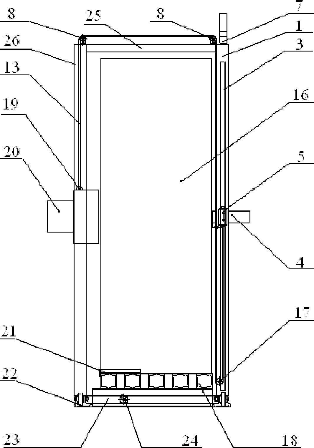
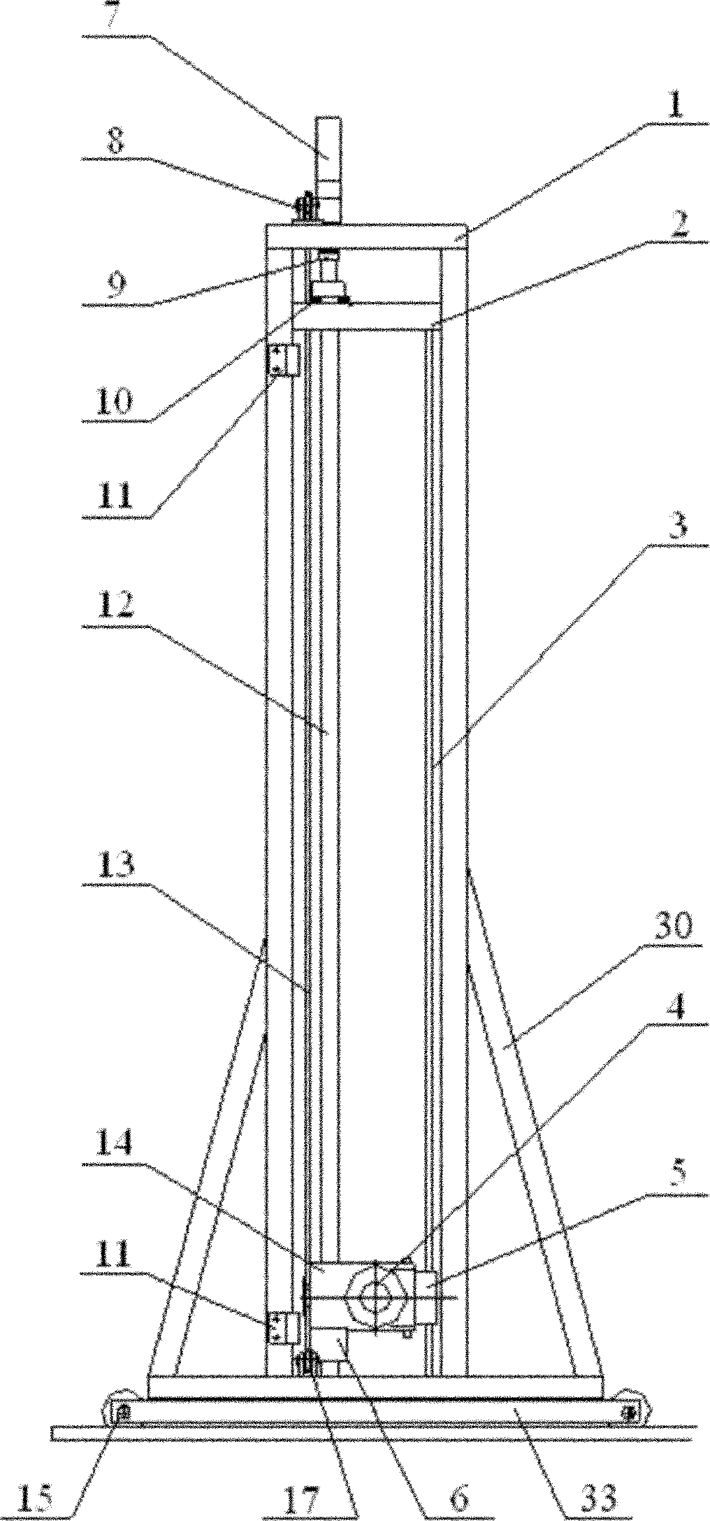
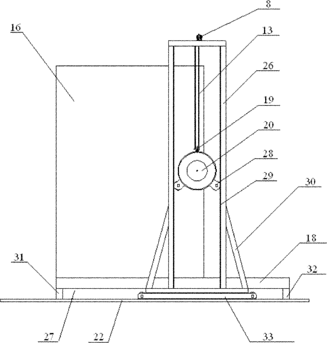
[0032] Such as figure 1 As shown, a non-destructive testing equipment for castings in this embodiment includes a gantry assembly, a Y-direction lifting assembly, a radiation receiving assembly 4, a source assembly 20, a pulley assembly, a chassis assembly and an X-direction moving assembly. Wherein, the gantry assembly includes the gantry right frame 1 and the gantry left frame 26, and the described source assembly 20 and the ray receiving assembly 4 are installed on the gantry right frame 1 and the gantry left frame 26 respectively, on the gantry right frame 1 and the gantry left frame 26 of the gantry assembly. A pulley assembly is installed on the left frame 26 of the gantry, and an X-direction moving assembly for horizontally moving the gantry assembly is installed below the gantry assembly.
[0033]The gantry assembly is the main supporting structure of the equipment of the present invention to provide support for the application source assembly 20 and the ray receiving a...
Embodiment 2
[0052] The difference between this embodiment and embodiment 1 is:
[0053] The Y-direction lifting assembly also includes a Y-direction movement mechanical limiter 2 and a thrust ball bearing 10. The Y-direction movement mechanical limiter 2 is a flat plate in the horizontal direction, which is fixed between the two vertical bars of the right frame 1 of the gantry , the lower surface is in contact with the upper surface of the Y-direction guide rail, and the Y-direction screw runs through the Y-direction movement mechanical limiter 2; the thrust ball bearing 10 is set on the Y-direction screw rod 12, and its upper surface is connected to the Y-direction shaft coupling 9 The lower surface is in contact with the upper surface of the Y-direction movement mechanical limiter 2.
[0054] The Y-direction movement mechanical limit device 2 can prevent the moving element from exceeding the capacity range after the equipment breaks down, and protects the device of the present invention...
Embodiment 3
[0056] The difference between this embodiment and the above two embodiments is:
[0057] The Y-direction lifting assembly also includes a set of Y-direction electronic limiters 11, which are respectively installed on the upper and lower ends of the vertical bar provided with the Y-direction screw on the right frame 1 of the gantry. The distance between the two is determined according to the height of the flaw-detected casting 16.
[0058] Similar to the Y-direction movement mechanical limit device 2, the Y-direction electronic limit device 11 limits the vertical travel range of the source assembly 20 and the radiation receiving assembly 4, and can be flexibly adjusted according to the size of the flaw-detected casting 16, The applicability of the device of the present invention to the flaw-detected castings 16 of different sizes is enhanced; in addition, the use of the Y-direction electronic limit device 11 can realize the limit function without contacting the hoop assembly 14 ...
PUM
| Property | Measurement | Unit |
|---|---|---|
| thickness | aaaaa | aaaaa |
| size | aaaaa | aaaaa |
| thickness | aaaaa | aaaaa |
Abstract
Description
Claims
Application Information
 - R&D
- Intellectual Property
- Life Sciences
- Materials
- Tech Scout
- Unparalleled Data Quality
- Higher Quality Content
- 60% Fewer Hallucinations
Browse by: Latest US Patents, China's latest patents, Technical Efficacy Thesaurus, Application Domain, Technology Topic, Popular Technical Reports.
© 2025 PatSnap. All rights reserved.Legal|Privacy policy|Modern Slavery Act Transparency Statement|Sitemap|About US| Contact US: help@patsnap.com


