touch panel

A technology of touch panel and touch area, which is applied in the direction of instruments, electrical digital data processing, input/output process of data processing, etc., and can solve problems affecting the overall appearance of electronic products, etc.

Active Publication Date: 2016-08-10
AU OPTRONICS CORP
View PDF6 Cites 0 Cited by
  • Summary
  • Abstract
  • Description
  • Claims
  • Application Information

AI Technical Summary

Problems solved by technology

The appearance design of the touch panel will be directly observed by the user and affect the overall appearance of these electronic products

Method used


Image

  • touch panel
  • touch panel
  • touch panel

Examples


no. 1 approach

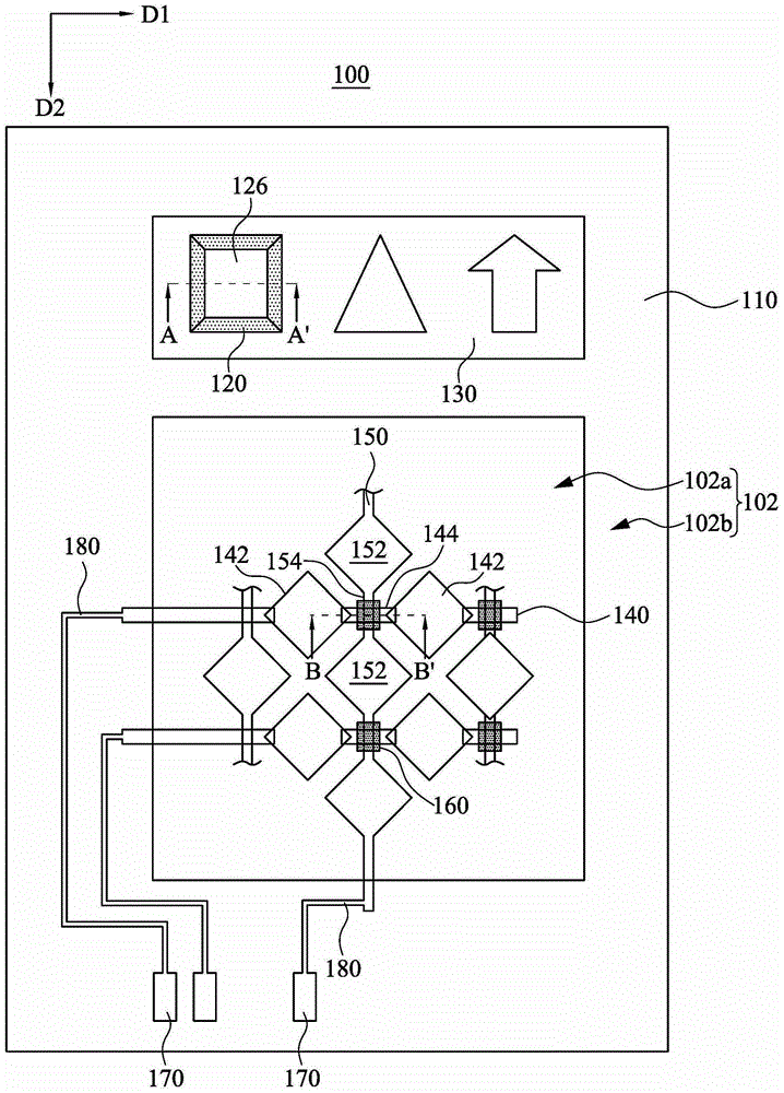
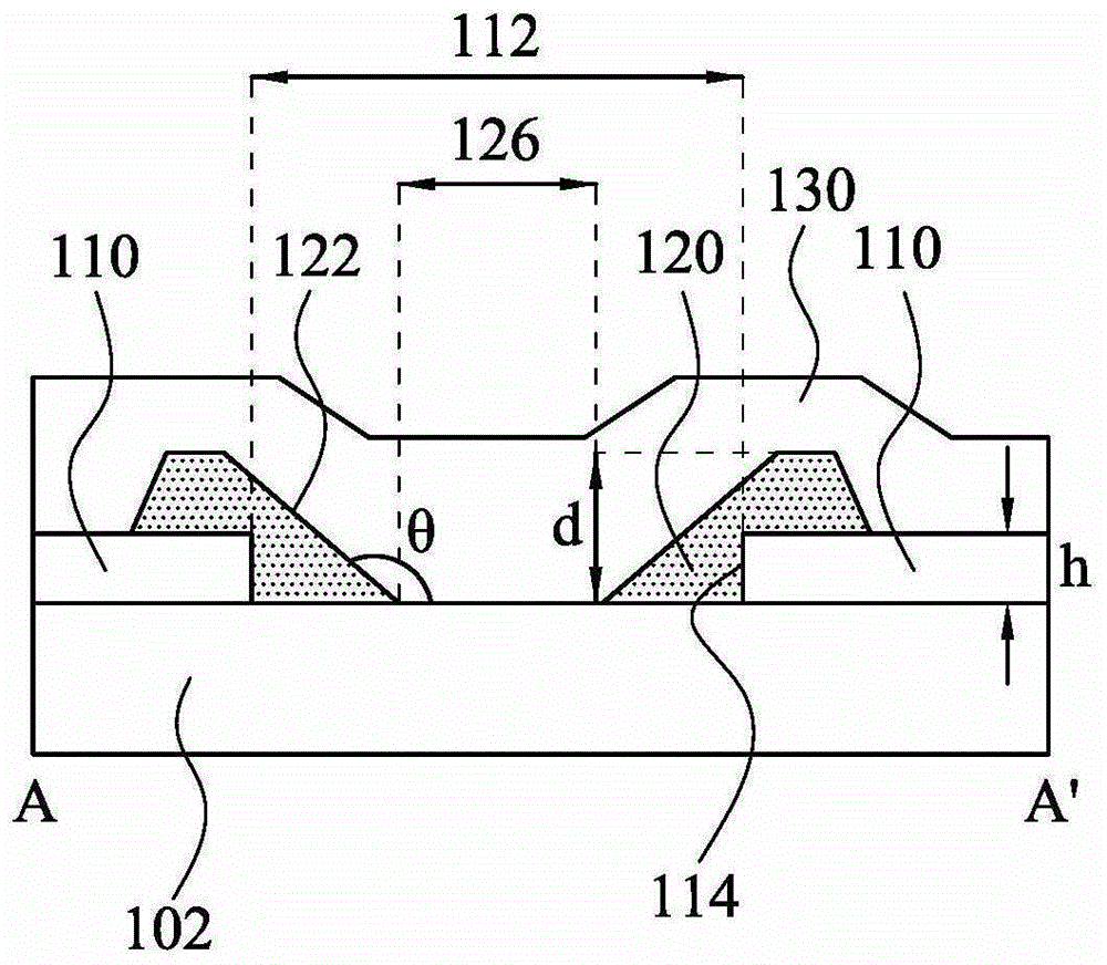
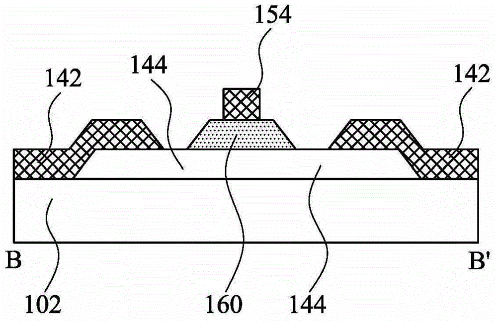
[0054] figure 1 To show a schematic top view of the touch panel 100 according to the first embodiment of the present invention, Figure 2A show figure 1 Schematic diagram of the section along the line AA', Figure 2B A schematic cross-sectional view along line BB' in Fig. 1 is shown. The touch panel 100 includes a substrate 102 , a light shielding layer 110 , a patterned transparent layer 120 , a reflective layer 130 , at least one first sensing series 140 and at least one second sensing series 150 .

[0055] Such as figure 1 As shown, the substrate 102 has a touch area 102a and a peripheral area 102b. The first sensing series 140 and the second sensing series 150 are arranged in the touch area 102a in a vertically staggered arrangement for detecting the position of the touch point. The number of the first sensing series 140 and the second sensing series 150 can be one or more, depending on the actual situation of the product. The peripheral area 102b is located at the p...

no. 2 approach

[0067] Figure 3A and Figure 3B It is a schematic cross-sectional view showing the touch panel according to the second embodiment of the present invention. The difference between this embodiment and the first embodiment lies in the shape and position of the patterned transparent layer 320 . In this embodiment, if Figure 3A As shown, the patterned light-transmitting layer 320 is an island pattern and is located in the patterned opening 112 . The island-shaped patterned light-transmitting layer 320 does not contact the sidewall 114 of the light-shielding layer 110 , so a second opening 128 is formed between the patterned light-transmitting layer 320 and the light-shielding layer 110 . The second opening 128 exposes a portion of the substrate 102 , and the second opening 128 is located between the sidewall 114 and the inclined sidewall 322 of the light shielding layer 110 , and surrounds the inclined sidewall 322 of the patterned transparent layer 320 . Figure 3B It is a s...

no. 3 approach

[0071] The difference between this embodiment and the first embodiment lies in the shape and position of the patterned transparent layer 420 . Figure 4 It is a schematic cross-sectional view showing the patterned opening 112 of the touch panel in this embodiment. In this embodiment, the patterned transparent layer 420 with different thicknesses is located in the patterned opening 112 and completely covers the patterned opening 112 . The patterned transparent layer 420 has a protruding portion 420a and a surrounding portion 420b, the surrounding portion 420b surrounds the protruding portion 420a, and the thickness H1 of the protruding portion 420a is greater than the thickness H2 of the surrounding portion 420b. In one example, the thickness H1 of the protruding portion 420 a is greater than the thickness h of the light shielding layer 110 , and the thickness H2 of the surrounding portion 420 b is smaller than the thickness h of the light shielding layer 110 . For example, th...


PUM


Abstract

A touch panel includes a substrate, a light-shielding layer, a patterned transparent layer, a reflecting layer, at least one first sensing series, and at least one second sensing series. The substrate has a touch sensing region and a peripheral region. The light-shielding layer is disposed in the periphery region. The light-shielding layer has a patterned opening and a sidewall adjacent to the patterned opening. The patterned opening is configured to provide a mark identifiable by human eyes. The patterned transparent layer is disposed in the peripheral region, and the patterned transparent layer covers a portion of the patterned opening. The patterned transparent layer has an inclined sidewall positioned in the patterned opening. The reflecting layer covers the inclined sidewall and the patterned opening. The first sensing series and the second sensing series are arranged in the touch sensing region to detect a position of a touch point.

Description

technical field [0001] The invention relates to a touch panel. Background technique [0002] In recent years, touch devices have been widely used in various electronic products, such as mobile phones, personal digital assistants, notebook computers and tablet computers. The display panel and touch device of these electronic products are combined to form a touch panel (touch panel), which becomes an efficient human-machine communication interface. Touch panels have tended to replace traditional input devices such as keyboards or mice. [0003] In many electronic products, the touch panel is usually arranged on or embedded in the display panel, so as to facilitate users to input information. The appearance design of the touch panel will be directly observed by the user and affect the overall appearance of these electronic products. Therefore, many researchers are devoting themselves to improving the aesthetic appearance of the touch panel. [0004] In addition to the aesth...

Claims


Application Information

Patent Timeline
Patent Type & Authority Patents(China)
IPC IPC(8): G06F3/041
CPCG06F3/0412G06F3/0446
Inventor 杨时韦陈安正周诗博
Owner AU OPTRONICS CORP
Why Eureka
Try Eureka