
Phase-locked frequency-stabilized gyrotron with periodic multi-conductor structure

A conductor structure and multi-conductor technology, which is applied in the field of high-power microwave and millimeter wave sources, can solve the problems of ineffective frequency stabilization, inability to achieve phase-locked and frequency-stabilized work, and injection signal conversion.

Inactive Publication Date: 2016-01-20
UNIV OF ELECTRONICS SCI & TECH OF CHINA
View PDF4 Cites 0 Cited by
  • Summary
  • Abstract
  • Description
  • Claims
  • Application Information

AI Technical Summary

Problems solved by technology

Because the temperature of the traditional gyrotron will rise during operation, the inner diameter of the resonant cavity will change, which will cause the frequency emission drift of the working mode, resulting in the frequency locking of the output frequency drift. The voltage and current control cannot effectively stabilize the frequency, so it is usually not used. Feedback phase-locking method, while injection phase-locking method
However, in order to obtain high power output, the gyrotron often works in a high-order mode. It is difficult to convert the injected signal into the required working mode by using the traditional gyrotron structure, so it is impossible to achieve phase-locked and frequency-stabilized work.

Method used


Image

  • Phase-locked frequency-stabilized gyrotron with periodic multi-conductor structure
  • Phase-locked frequency-stabilized gyrotron with periodic multi-conductor structure
  • Phase-locked frequency-stabilized gyrotron with periodic multi-conductor structure

Examples


Embodiment 1

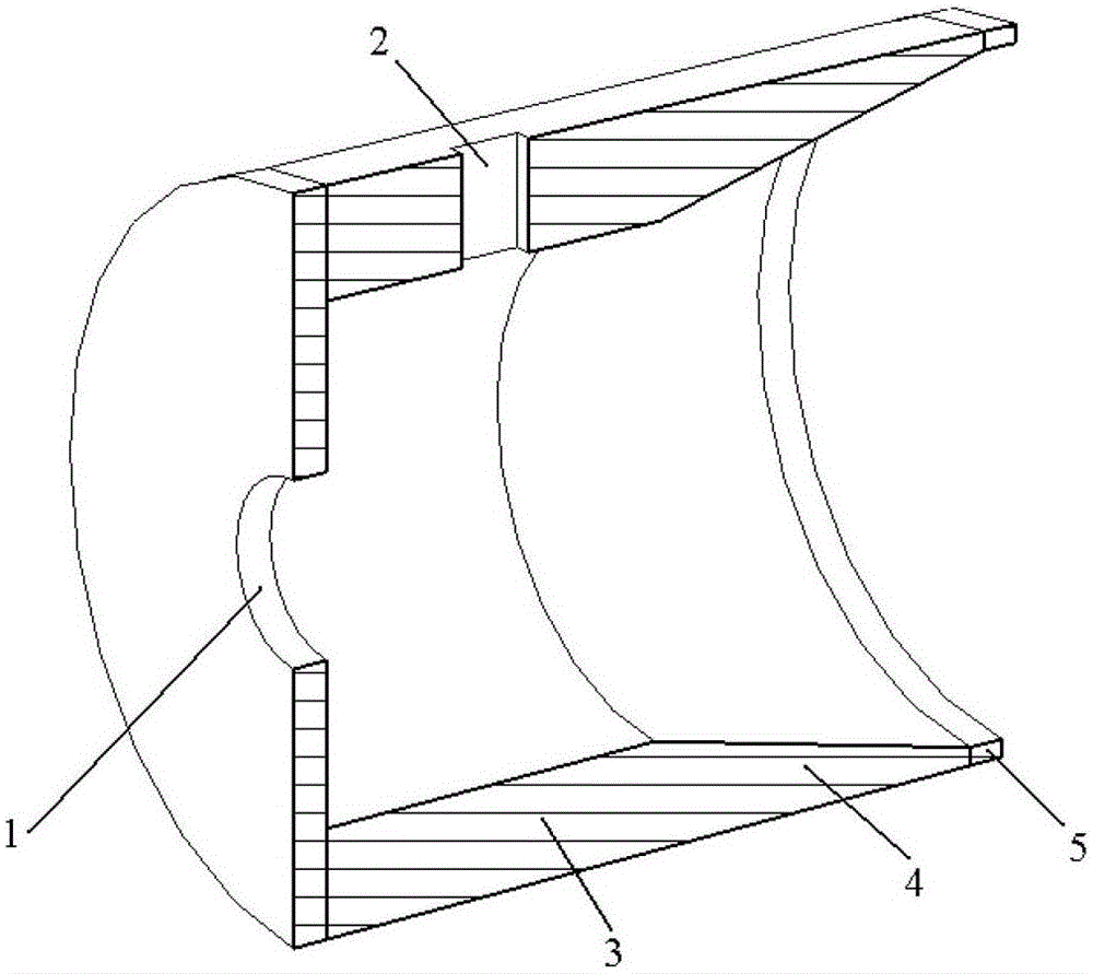
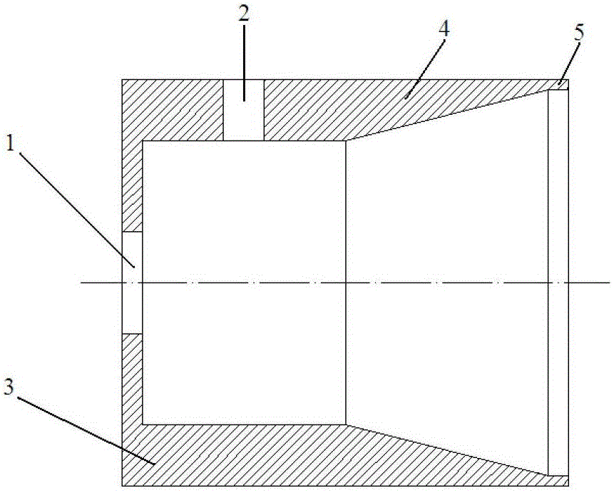
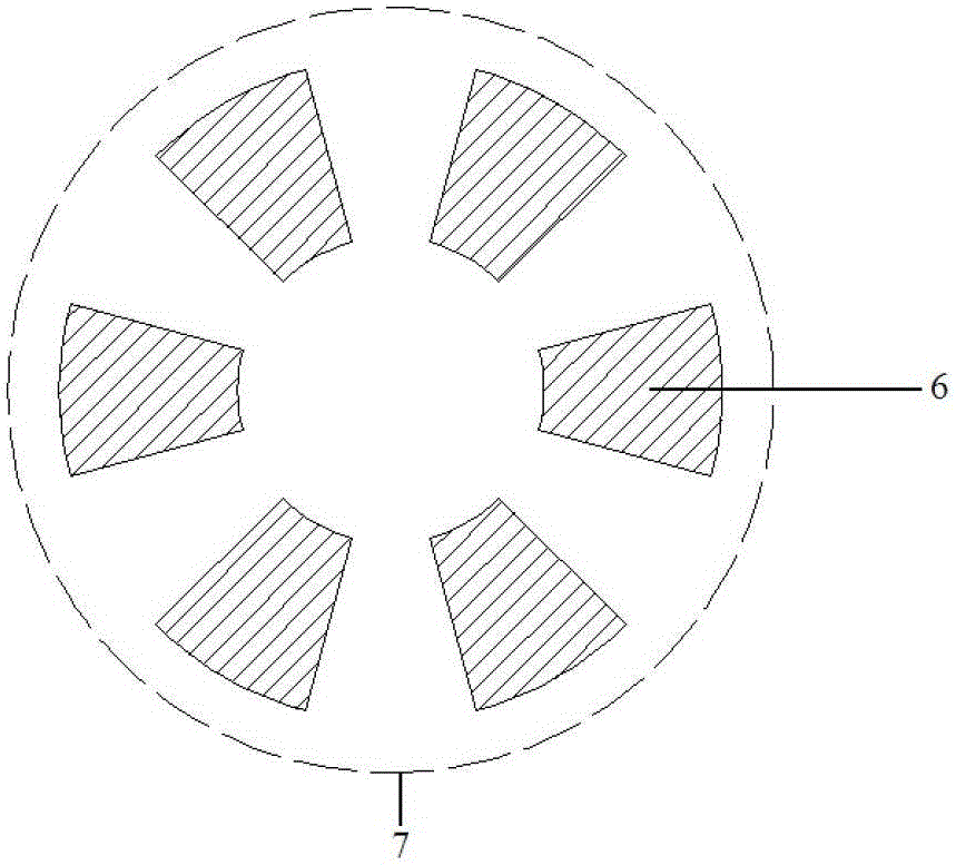
[0022] like Figure 5 As shown, a resonant cavity used for phase locking and frequency stabilization of a gyrotron. Metal conductors 6 in the resonant cavity are arranged periodically along the angular direction to form a one-dimensional angular multi-conductor structure 7. The interior of the one-dimensional angular multi-conductor structure 7 is a hollow structure to form the electron beam channel 1 of the gyrotron. The external resonant cavity outer wall 3 of the conductor structure 7 has an injection waveguide hole 2 on the resonant cavity outer wall 3, the injection waveguide hole 2 is a rectangular waveguide hole, and the injection waveguide hole 2 is located in the gap of the metal conductor 6.

[0023] The phase-locked signal is injected into the one-dimensional angular multi-conductor structure 7 through the injection waveguide hole 7. Since the metal conductors 6 in the one-dimensional angular multi-conductor structure 7 are arranged periodically in a one-dimensional...

Embodiment 2

[0025] like Figure 6 As shown, a resonant cavity used for phase locking and frequency stabilization of a gyrotron. The metal conductors 6 in the resonant cavity are arranged periodically along the angular direction and the radial direction to form a two-dimensional angular and radial multi-conductor structure 8, and the interior of the two-dimensional angular and radial multi-conductor structure 8 is a hollow structure to form the electronic structure of the gyrotron. The beam channel 1, the outer wall 3 of the external resonant cavity of the two-dimensional angular and radial multi-conductor structure 8, the outer wall 3 of the resonant cavity has an injection waveguide hole 2, the injection waveguide hole 2 is a rectangular waveguide hole, and the position of the injection waveguide hole 2 is located in the metal In the gap of conductor 6.

[0026] The phase-locked signal is injected into the two-dimensional angular and radial multi-conductor structure 8 through the inject...


PUM


Abstract

A phase-locked frequency-stabilized gyrotron with a periodic multi-conductor structure belongs to the technical field of high-power microwave and millimeter wave sources. The invention includes a resonator with an electron beam channel and an injection waveguide hole, an output gradient waveguide, and an output uniform waveguide, and is characterized in that, in the resonant cavity of the resonator, at least 3 Conductor structures, the injection waveguide holes are located between two adjacent conductor structures. The beneficial effect of the present invention is that the injection signal can be effectively converted into the working mode of the gyrotron through the multi-conductor structure, so that the electron beam is forced to perform modulation according to the injection signal, so that the electron beam can only produce modulation of the injection signal in the resonant cavity Generate an output, so that the output signal achieves phase-locking and frequency stabilization.

Description

technical field [0001] The invention relates to a phase-locked frequency-stabilized gyrotron with a periodic multi-conductor structure, belonging to the technical field of high-power microwave and millimeter wave sources. Background technique [0002] In the late 1950s, Australian astronomer Twiss proposed a new concept of electron cyclotron resonance stimulated radiation through the observation of the ionosphere absorbing electromagnetic waves. At about the same time, the American scientist Schneider and the former Soviet scientist Gaponov also independently proposed a new concept of the interaction between the spiral electron beam moving in the magnetic field and the electromagnetic wave when considering the relativistic effect. In the mid-1960s, the American scientist Hirshfield fully confirmed the mechanism of the electron cyclotron maser through experiments. On this basis, scientists in the former Soviet Union successfully developed a microwave device-gyrotron with the...

Claims


Application Information

Patent Timeline
Patent Type & Authority Patents(China)
IPC IPC(8): H01J25/02H01J23/02
Inventor 鄢扬傅文杰
Owner UNIV OF ELECTRONICS SCI & TECH OF CHINA
Learn More