
Automatic Grinding Robot

A robotic and automatic technology, applied in the direction of grinding machines, grinding workpiece supports, grinding/polishing equipment, etc., can solve the problems of low efficiency and achieve the effect of improving production efficiency and equipment adaptability

Active Publication Date: 2015-09-09
永红保定铸造机械有限公司
View PDF7 Cites 0 Cited by
  • Summary
  • Abstract
  • Description
  • Claims
  • Application Information

AI Technical Summary

Problems solved by technology

[0002] In the factories that produce small castings in large quantities in my country, most of the cleaning process adopts sand cleaning, drum shakeout, dewatering riser, manual finishing, fine throwing, anti-rust treatment, etc. From sand falling to dewatering riser, it is basically a continuous operation to pour out the riser. The castings after the mouth are transferred to the manual finishing station using a mechanized plate conveyor or basket (bucket). There are two forms of manual finishing: one is grinding with a grinder, and the other is cleaning with a hydraulic casting cleaning machine. In some developed countries, the casting finishing of advanced foundry enterprises is to use robots to hold the castings and grind them on various fixed grinding equipment. The grinding curve is completely set by the equipment in advance, and the surface of the cleaned castings is consistent. The cleaning features of small castings are: the cleaning equipment is fixed, and the castings are directly held by humans or robots for cleaning after batch transfer. Although large batches of castings can be processed, the grinding of different surfaces of castings needs to be transferred to different equipment stations for processing. ,low efficiency

Method used


Image

  • Automatic Grinding Robot

Examples


Embodiment Construction

[0014] The present invention will be further described in detail below in conjunction with the accompanying drawings and specific embodiments.

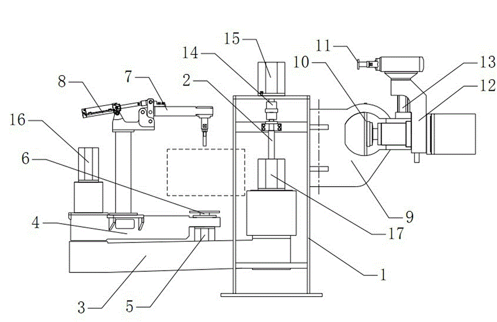
[0015] In summary, the present invention discloses a figure 1 The shown automatic grinding robot includes a frame 1, a grinding device, a workpiece positioning device, a workpiece pressing device and a control device, and the grinding device is rotatably arranged on one side of the frame 1 by means of a rotating frame, and the The workpiece positioning device includes a lifting mechanism and a swing arm mechanism. The end of the swing arm mechanism is provided with a tray 6 and an autorotation motor 5 for driving the rotation of the tray 6. The workpiece pressing device is fixed at the end of the swing arm, and the workpiece is clamped The end of the device is located directly above the pallet 6, and the rotary arm mechanism in the workpiece positioning device is driven to rotate by the second motor and the third motor. The two sets o...


PUM


Abstract

The invention discloses an automatic grinding robot, which relates to the technical field of casting grinding equipment, and comprises a rack, a grinding device, a workpiece locating device, a workpiece hold-down device and a control device, wherein the grinding device is rotatably arranged on one side of the rack through a rotary support; the workpiece locating device comprises a lifting mechanism and a spiral arm mechanism; a tray and a rotation motor for driving the tray to rotate are arranged on the tail end of the spiral arm mechanism; the workpiece hold-down device is fixedly arranged on the tail end of a spiral arm; and the tail end of the workpiece hold-down device is located right above the tray. The automatic grinding robot has the advantages that due to the lifting mechanism, the spiral arm mechanism and the hold-down mechanism, the location of a workpiece is realized; due to the tray and the rotation motor, the rotary location of the workpiece is realized; and two sets of rotatable grinding wheel grinding devices are arranged and are optional, so that surfaces of different castings can be ground in all directions, and the production efficiency and the equipment adaptability are greatly improved.

Description

technical field [0001] The invention relates to the technical field of casting grinding equipment, in particular to an automatic grinding robot. Background technique [0002] In the factories that produce small castings in large quantities in my country, most of the cleaning processes adopt sand cleaning, drum shakeout, de-casting riser, manual finishing, fine throwing, anti-rust treatment, etc. From sand-out to de-gating and de-rising, it is basically a continuous operation. The castings after the mouth are transferred to the manual finishing station using a mechanized plate conveyor or basket (bucket). There are two forms of manual finishing: one is grinding with a grinder, and the other is cleaning with a hydraulic casting cleaning machine. In some developed countries, the casting finishing of advanced foundry enterprises is to use robots to hold the castings and grind them on various fixed grinding equipment. The grinding curve is completely set by the equipment in advance...

Claims


Application Information

Patent Timeline
Patent Type & Authority Patents(China)
IPC IPC(8): B24B19/00B24B41/06
Inventor 李彦青李福
Owner 永红保定铸造机械有限公司
Learn More