A grinding device for polishing wooden discs
A round block and wooden technology, which is applied in the field of polishing devices for wooden round blocks, to achieve the effects of reducing labor intensity, improving polishing efficiency, and reducing labor load
- Summary
- Abstract
- Description
- Claims
- Application Information
AI Technical Summary
Problems solved by technology
Method used
Image
Examples
Embodiment 1
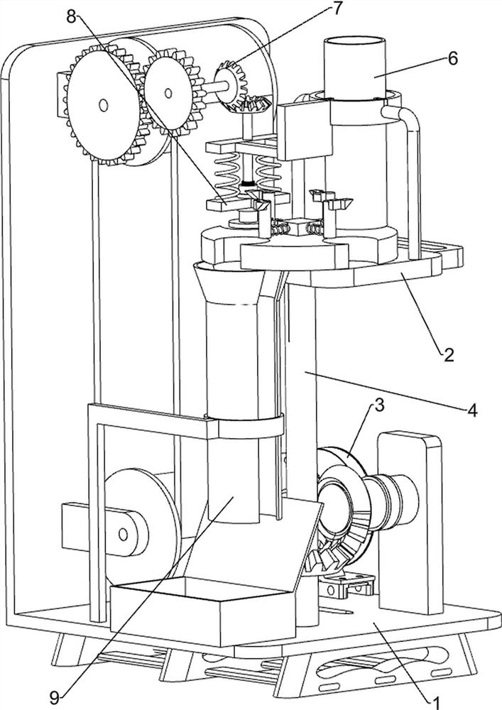
[0030] A grinding device for polishing wooden discs, such as Figure 1 to Figure 5 As shown, it includes a bottom plate 1, a mounting frame 2, a grinding mechanism 3, a feeding mechanism 4 and a feeding mechanism 6. The upper part of the bottom plate 1 is connected with a mounting frame 2, and a grinding mechanism 3 and a feeding mechanism 4 are respectively installed on the bottom plate 1. The feeding mechanism 4 is connected with the grinding mechanism 3 in a driving manner, and a blanking mechanism 6 is installed on the mounting frame 2 .
[0031] The grinding mechanism 3 includes a low-speed motor 31, a power rotating rod 32, a fixed plate 33, a fan-shaped bevel gear 34, a flat belt group 35 and a grinding belt group 36, and a low-speed motor 31 is installed on the left rear side of the lower part of the bottom plate 1. The output of the low-speed motor 31 The shaft is connected with a power rotating rod 32, a fixed plate 33 is installed on the lower right rear side of the...
Embodiment 2
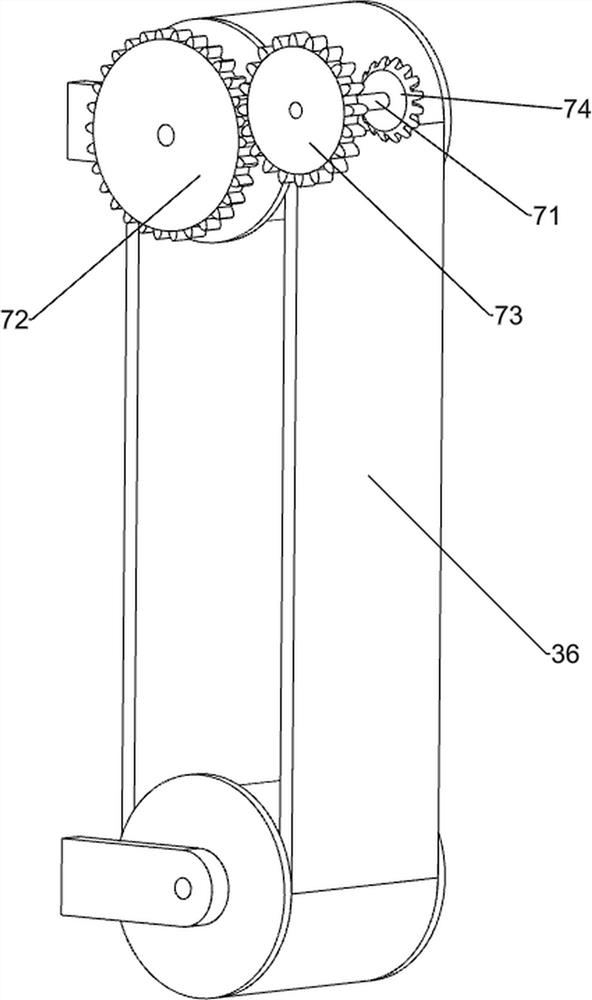
[0036] On the basis of Example 1, as Figure 5 , Image 6 and Figure 7 As shown, it also includes a linkage mechanism 7, the linkage mechanism 7 includes a connecting shaft 71, a first gear 72, a second gear 73 and a second bevel gear 74, the upper part of the bottom plate 1 is rotatably connected with a connecting shaft 71, and the grinding belt group 36 The upper transmission shaft is connected with a first gear 72 , the front end of the connecting shaft 71 is connected with a second gear 73 , the second gear 73 meshes with the first gear 72 , and the rear end of the connecting shaft 71 is connected with a second bevel gear 74 .
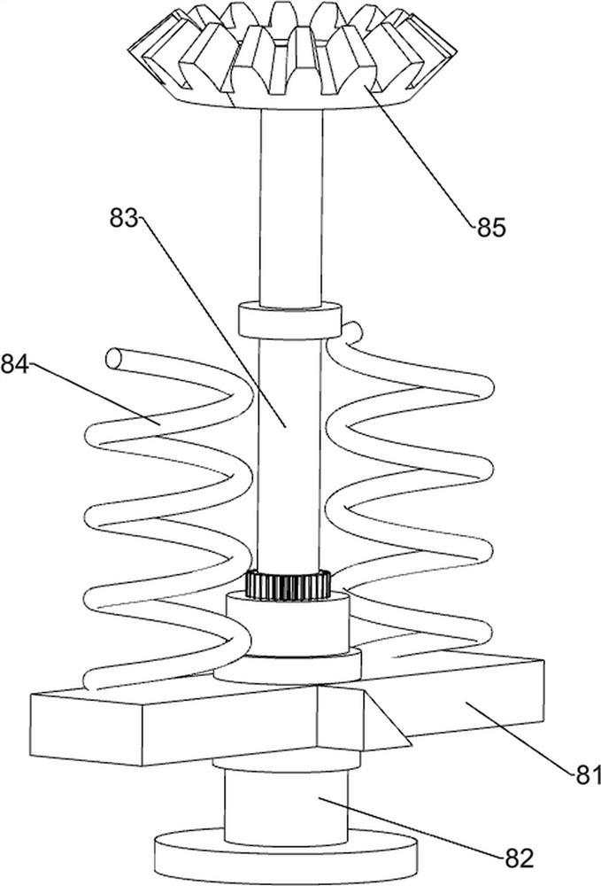
[0037]It also includes a rotating mechanism 8. The rotating mechanism 8 includes a pressing top block 81, a rotating top plate 82, a toothed rotating shaft 83, a second spring 84, a third bevel gear 85, a hole positioning block 86, an extrusion limit frame 87 and The first spring 88, two second springs 84 are symmetrically connected to the botto...
Embodiment 3
[0040] On the basis of Example 2, as Figure 8 As shown, it also includes a material receiving mechanism 9. The material receiving mechanism 9 includes a material receiving box 91, an L-shaped fixing frame 92 and a feeding guide 93. The lower right front side of the bottom plate 1 is connected with a material receiving box 91, and the lower part of the bottom plate 1 The left front side is connected with an L-shaped fixing frame 92 , and the upper part of the L-shaped fixing frame 92 is connected with a blanking guide sliding pipe 93 , and the blanking guide sliding pipe 93 is located above the material receiving box 91 .
[0041] The polished wooden blocks then fall into the unloading guide slide pipe 93, and then slide down into the receiving box 91 through the unloading guide slide pipe 93, so that the polished wooden blocks can be collected without the need for Manually collect the wooden blocks after grinding, which can further reduce the amount of labor and labor intensi...
PUM
 Abstract
Description
Claims
Application Information
 - R&D
- Intellectual Property
- Life Sciences
- Materials
- Tech Scout
- Unparalleled Data Quality
- Higher Quality Content
- 60% Fewer Hallucinations
Browse by: Latest US Patents, China's latest patents, Technical Efficacy Thesaurus, Application Domain, Technology Topic, Popular Technical Reports.
© 2025 PatSnap. All rights reserved.Legal|Privacy policy|Modern Slavery Act Transparency Statement|Sitemap|About US| Contact US: help@patsnap.com


