3D (Three-dimensional) printing method of engineering structure

A technology of engineering structure and 3D printing, applied in manufacturing tools, ceramic molding machines, etc., can solve problems such as high threshold, increased cost, difficulty of layered printing, etc.

Active Publication Date: 2013-10-02
BEIJING JIAOTONG UNIV
View PDF4 Cites 40 Cited by
  • Summary
  • Abstract
  • Description
  • Claims
  • Application Information

AI Technical Summary

Problems solved by technology

However, the application of traditional 3D printing in the field of engineering structures has obviously encountered a high threshold, mainly because engineering structures are mostly concrete structures, such as prestressed concrete structures, steel-concrete composite structures, etc. Steel bars, steel beams, steel cylinders, etc. Obviously, it is quite difficult to print these in layers in the form of powder, and the cost will increase a lot

Method used


Image

  • 3D (Three-dimensional) printing method of engineering structure
  • 3D (Three-dimensional) printing method of engineering structure
  • 3D (Three-dimensional) printing method of engineering structure

Examples


Embodiment 1

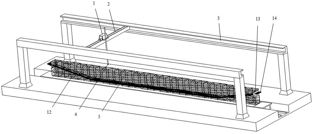
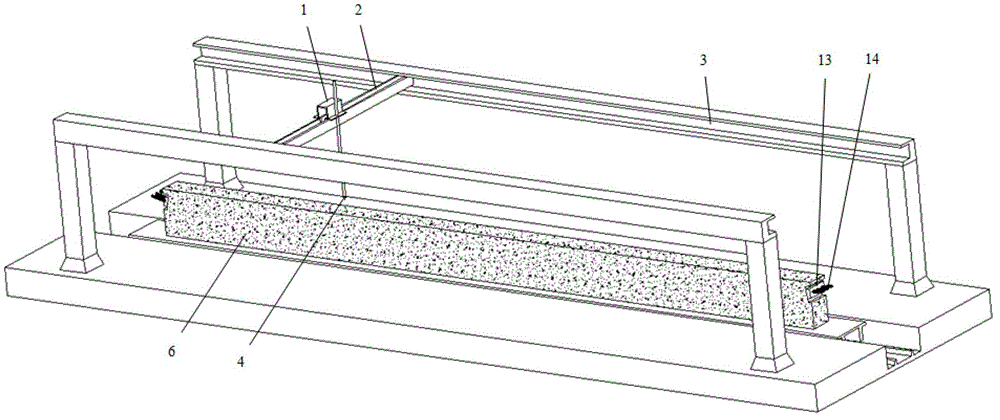
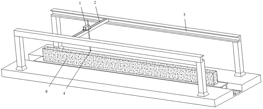
[0035] Example 1 A 3D printing method for a prestressed concrete prefabricated structure

[0036] Example description: A prestressed concrete beam with a span of 32m is manufactured by 3D printing method, such as Figure 1~Figure 4 shown. According to the design, pre-process and manufacture the reinforcement skeleton, position and install prestressed tendon channels, prestress anchors and other accessories on the skeleton, and finally form a complete reinforcement skeleton. Move the reinforced skeleton to the 3D printing platform, and control the printing head that can move and rotate in three directions according to the 3D model of the prestressed concrete beam built in the computer, that is, the spray head that can control the movement and rotation in three directions, and carry out layer by layer. Print. During the printing process, the printing time of each layer was controlled according to the initial setting and final setting ages of the concrete to form a reinforced c...

Embodiment 2

[0041] Embodiment 2 A 3D printing method of a steel-concrete composite structure

[0042] Example: A steel-concrete composite beam with a span of 32m, the steel beam is an I-beam, and it is manufactured by 3D printing method, such as Figure 5~Figure 7 shown. Manufacture the steel beam skeleton in advance according to the design, and then move the steel beam skeleton to the 3D printing platform. According to the 3D model of the steel-concrete composite structure pre-established in the computer, control the printing head that can move and rotate in three directions, that is, Control the three-way moving and rotating jet head to print in layers. During the printing process, the printing time of each layer was controlled according to the initial setting and final setting age of the concrete, and finally a steel-concrete composite beam with a span of 32m was formed. The specific implementation steps are as follows:

[0043] Step 1 Establish a 3D model of the steel-concrete compos...

Embodiment 3

[0046] Embodiment 3 A 3D printing method for prestressed steel cylinder concrete pipe

[0047] Example description: A prestressed steel cylinder concrete pipe with an inner diameter of 3m is manufactured by 3D printing method, such as Figure 8~Figure 11 shown. Manufacture the steel cylinder skeleton in advance according to the design, then move the steel cylinder skeleton to the 3D printing platform, and control the printing head that can move and rotate in three directions according to the three-dimensional model of the prestressed steel cylinder concrete pipe built in the computer, namely The spray head that can control the three-way movement and rotation, sprays concrete inside and outside the steel cylinder, and prints in layers. During the printing process, the printing time of each layer is controlled according to the initial setting and final setting age of the concrete. After the concrete layer is formed, wrap the circumferential prestressed tendons on the outer sur...


PUM

PropertyMeasurementUnit
radiusaaaaaaaaaa

Abstract

The invention relates to a 3D (Three-dimensional) printing method of an engineering structure, and belongs to the technical field of engineering. The method comprises the following steps of: manufacturing a framework such as reinforcing steel bars, girders and steel cylinders of the engineering structure firstly according to a three-dimensional model of the engineering structure; and then, spraying concrete on the surface of the framework or inside the framework by a 3D printer layer by layer, wherein the whole printing process is precisely controlled by a computer system, so that the three-dimensional engineering structure is quickly manufactured. The method provided by the invention has the beneficial effects that the method overcomes the defect that conventional engineering structure manufacturing method requires a lot of templates, manpower and working hours, and the manufacturing precision and quality often difficultly satisfy the demand. The method is a major innovation and has important meaning for application of 3D printing in the engineering field.

Description

technical field [0001] The invention relates to a 3D printing method for engineering structures, which is applied to three-dimensional rapid production of various engineering structures in the engineering field. Background technique [0002] The traditional 3D printing technology is based on the computer 3D design model, through the software layered discrete and numerical control molding system, using laser beams, hot-melt nozzles, etc. to process special materials such as metal powder, ceramic powder, plastic, and cell tissue layer by layer. Accumulated and bonded, and finally superimposed and formed to produce a physical product. This digital manufacturing mode does not require complex processes or a lot of manpower. It can directly generate parts of any shape from computer graphics data, and has high precision and quality. Therefore, 3D printing will be a revolution in manufacturing. [0003] Engineering structures include civil engineering structures, hydraulic engineer...

Claims


Application Information

Patent Timeline
Patent Type & Authority Applications(China)
IPC IPC(8): B28B23/04
Inventor 朱尔玉施明源朱力
Owner BEIJING JIAOTONG UNIV
Why Eureka
Try Eureka