Automatic compensation butterfly valve

An automatic compensation and butterfly valve technology, which is applied in the direction of lifting valves, valve devices, engine components, etc., can solve the problems of unsealed valves, increased opening torque, and valve stem damage, so as to achieve reliable sealing performance, reduce opening torque, and increase service life. The effect of longevity

Inactive Publication Date: 2013-10-02
TIANJIN BAILIZHANFA GRP
View PDF7 Cites 6 Cited by
  • Summary
  • Abstract
  • Description
  • Claims
  • Application Information

AI Technical Summary

Problems solved by technology

[0002] Butterfly valves are divided into soft-sealed and hard-sealed structures. The sealing surface of hard-sealed butterfly valves is made of stainless steel and stainless steel. It has a fireproof function and is suitable for high-pressure and large-caliber occasions. However, its production process is complicated, assembly is difficult, and the manufacturing cost is high. ; Although the structure of the soft-sealing butterfly valve has the characteristics of simple structure, convenient manufacture, low cost, and reliable operation, it has the following defects: 1. When the working pressure is above 5.0 MPa, the initial compression of the valve seat cannot reach the high-pressure seal. Or when the high pressure seal is reached, the opening torque increases, increasing the possibility of the valve stem being damaged
2. After long-term use and storage, the fluoroplastic or rubber valve seat has cold deformation, the elasticity decreases, the opening torque increases, and the valve cannot be sealed; 3. The soft-sealing butterfly valve does not have fire protection function and cannot adapt to the requirements of working conditions.

Method used


Image

  • Automatic compensation butterfly valve
  • Automatic compensation butterfly valve

Examples


Embodiment Construction

[0015] The present invention will be further described in detail below in conjunction with the accompanying drawings and through specific embodiments. The following embodiments are only descriptive, not restrictive, and cannot limit the protection scope of the present invention.

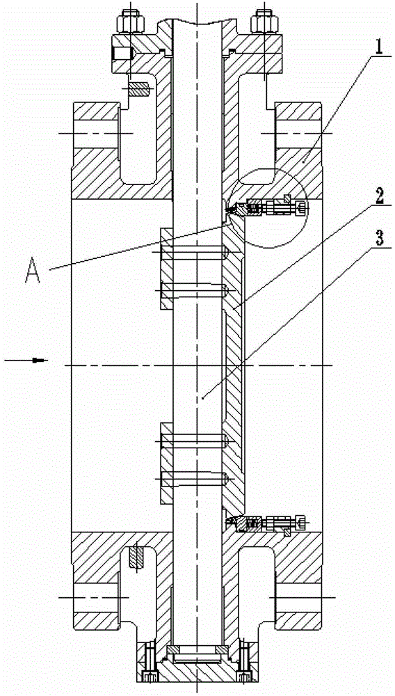
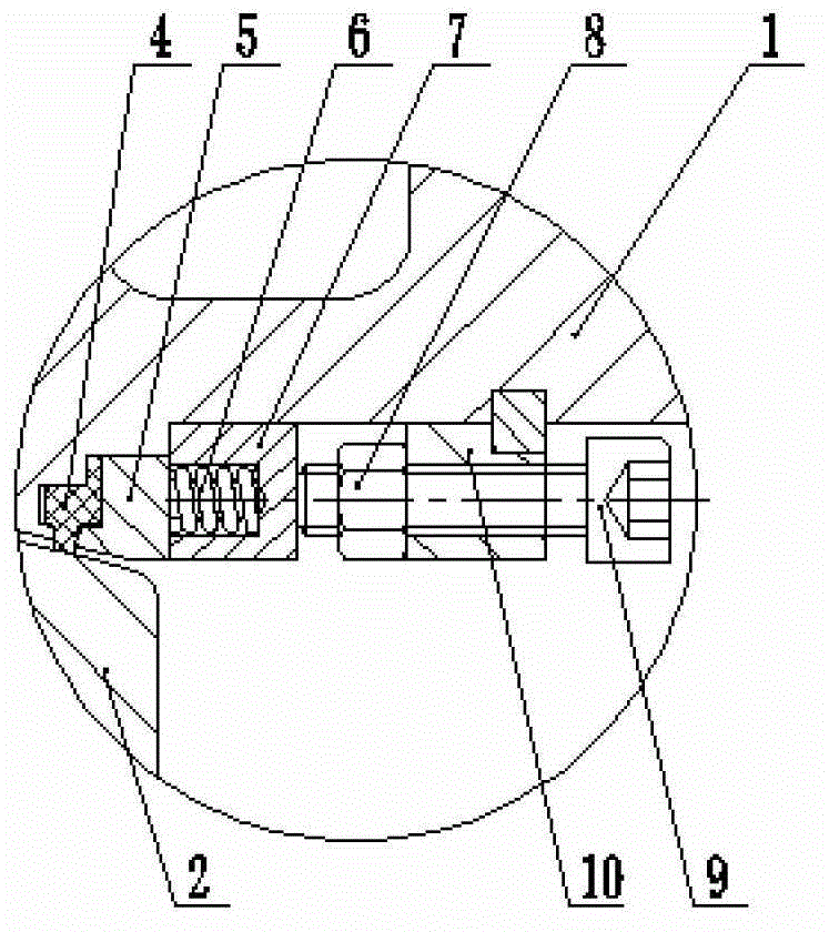
[0016] An automatic compensation butterfly valve, including a valve body 1, a valve stem 3, a butterfly plate 2 and a valve seat sealing ring 4, as attached figure 1 The valve body shown in the figure has a horizontal medium channel, and the arrow in the attached drawing shows the flow direction of the medium. The butterfly plate controls the closing and opening of the medium channel in the valve body; a valve seat sealing ring is coaxially installed on the inner wall of the medium channel of the valve body on the side where the butterfly plate is installed, and the valve seat sealing ring is frictionally sealed with the butterfly plate, and the valve seat sealing ring The material is fluorine plasti...


PUM


Abstract

The invention relates to an automatic compensation butterfly valve which comprises a valve body, a valve rod, a butterfly plate and a valve seat sealing ring. A horizontal medium channel is arranged in the valve body, the valve rod is longitudinally arranged in the valve body, and one side of the valve rod in the valve body is fixedly provided with the butterfly plate which rotates under the driving of the valve rod. The valve seat sealing ring is coaxially arranged on the inner wall of the medium channel on one side, where the butterfly plate is arranged, of the valve body, and the valve seat sealing ring is sealed with the butterfly plate in a rubbing mode. The valve seat sealing ring is arranged on the valve body through an elastic compensation device, fixing seats are fixedly arranged between the inner wall of the valve body on the valve seat sealing ring side and the valve seat sealing ring horizontally at intervals. The fixing seats are horizontally provided with screws which are arranged on the fixing seats through guide regulation by nuts, the screws butt against a spring seat horizontally, and the spring seat butts against a pressing ring horizontally. The pressing ring horizontally butts against the valve seat sealing ring. The automatic compensation butterfly valve is simple in structure, scientific in design, reliable in sealing performance, long in service life, small in opening torque, and suitable for various occasions.

Description

technical field [0001] The invention belongs to the field of butterfly valves, in particular to an automatic compensation butterfly valve. Background technique [0002] Butterfly valves are divided into soft-sealed and hard-sealed structures. The sealing surface of hard-sealed butterfly valves is made of stainless steel and stainless steel. It has a fireproof function and is suitable for high-pressure and large-caliber occasions. However, its production process is complicated, assembly is difficult, and the manufacturing cost is high. ; Although the structure of the soft-sealing butterfly valve has the characteristics of simple structure, convenient manufacture, low cost, and reliable operation, it has the following defects: 1. When the working pressure is above 5.0 MPa, the initial compression of the valve seat cannot reach the high-pressure seal. Or when the high-pressure seal is reached, the opening torque increases, increasing the possibility of the valve stem being dama...

Claims


Application Information

Patent Timeline
Patent Type & Authority Applications(China)
IPC IPC(8): F16K1/226F16K1/32
Inventor 乔玉凤宋保明付永召
Owner TIANJIN BAILIZHANFA GRP
Why Eureka
Try Eureka