
Electric splitting device for solar cells

A technology of solar cells and fragments, which is applied in the direction of circuits, electrical components, sustainable manufacturing/processing, etc., and can solve the problems of high fragmentation rate and low efficiency of artificial fragmentation

Active Publication Date: 2016-12-28
TRINA SOLAR CO LTD
View PDF4 Cites 0 Cited by
  • Summary
  • Abstract
  • Description
  • Claims
  • Application Information

AI Technical Summary

Problems solved by technology

At present, the breaking is done manually, and there is no mechanism or automation equipment to replace this manual work.
The efficiency of artificial fragmentation is low and the fragmentation rate is high. The research and development of automatic fragmentation mechanism has become the demand of new photovoltaic technology

Method used


Image

  • Electric splitting device for solar cells
  • Electric splitting device for solar cells
  • Electric splitting device for solar cells

Examples


Embodiment Construction

[0019] In order to make the content of the present invention easier to understand clearly, the present invention will be described in further detail below according to specific embodiments in conjunction with the accompanying drawings,

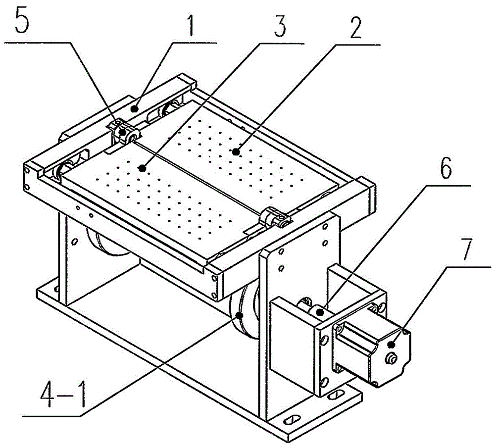
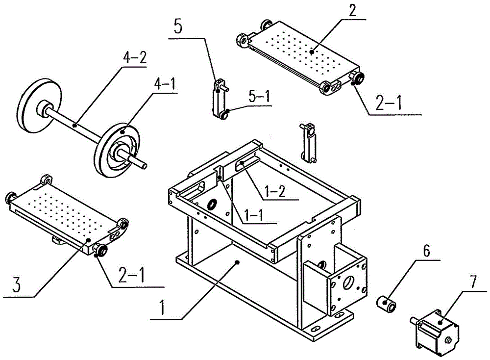
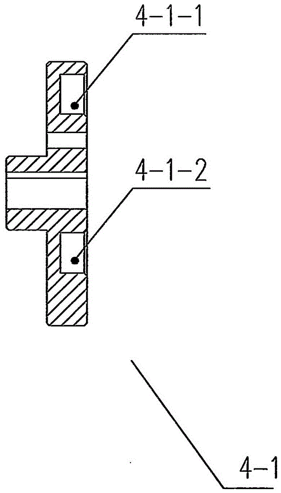
[0020] Such as Figure 1~7 As shown, a kind of solar cell electric splitting device, it comprises frame 1, left split plate 3, right split plate 2 and the connecting rod 5 that slides on the frame 1 and drives the connecting rod 5 to do on the frame 1. Cam drive mechanism that reciprocates linearly up and down, one end of the left split plate 3 is slidingly fitted on one side of the frame 1, one end of the right split plate 2 is slipped on the other side of the frame 1, the other end of the left split plate 3, The other end of the right split plate 2 and one end of the connecting rod 5 are hinged together.

[0021] Such as figure 2 As shown, there is a vertical chute 1-1 in the middle of the frame 1, and the connecting rod 5 is slidingly fi...


PUM


Abstract

The invention discloses a solar cell sheet electric sheet-splitting device. The solar cell sheet electric sheet-splitting device comprises a rack, a left sheet-splitting plate, a right sheet-splitting plate, connecting pull rods which are in slide fit with the rack, and a cam driving mechanism which drives the connecting pull rods to perform vertical reciprocating linear motion on the rack; one end of the left sheet-splitting plate is in slide fit with one side of the rack; one end of the right sheet-splitting plate is in slide fit with the other end of the rack; and the other end of the left sheet-splitting plate, the other end of the right sheet-splitting plate and one end of each connecting pull rod are hinged together. With the solar cell sheet electric sheet-splitting device of the invention adopted, the standardization and automation of solar cell sheet splitting can be realized, and randomness and errors caused by human can be eliminated, and sheet-splitting efficiency and sheet-splitting qualified rate can be improved.

Description

technical field [0001] The invention relates to an electric splitting device for solar cells, which belongs to the technical field of solar cells. Background technique [0002] At present, photovoltaic solar crystalline silicon cells have developed into the heart of green new energy, and the photovoltaic industry has become large-scale. Improving the power generation efficiency of crystalline silicon cells has become the goal pursued by the industry. The existing crystalline silicon cells are the main The specifications and sizes are: polycrystalline cell 156mm×156mm, or monocrystalline cell 125mm×125mm. In order to improve the power generation efficiency of the cell, the new process of the cell requires the shape of the existing cell to be divided, such as polycrystalline 156mm×125mm 156mm is divided into 156mm×78mm, divided into two. The segmentation process is divided into two steps, one is to perform laser tangent (the battery sheet is not broken, and the laser does not...

Claims


Application Information

Patent Timeline
Patent Type & Authority Patents(China)
IPC IPC(8): H01L31/18H01L21/304
CPCY02P70/50
Inventor 吴正同朱留生
Owner TRINA SOLAR CO LTD
Learn More