Test device for the characteristics of the joint surface of the ball and the raceway

A technology for testing devices and joint surfaces, which is applied in the testing of machines/structural components, measuring devices, testing of mechanical components, etc., and can solve problems such as difficulties in testing contact characteristics

Active Publication Date: 2016-02-24
SUZHOU FURUTA AUTOMATION TECH
View PDF5 Cites 0 Cited by
  • Summary
  • Abstract
  • Description
  • Claims
  • Application Information

AI Technical Summary

Problems solved by technology

[0004] The purpose of the present invention is to provide a test device for the characteristics of the joint surface of the ball and the raceway, which solves the problem of difficulty in testing the contact characteristics of the joint surface composed of the ball and the raceway in the prior art

Method used


Image

  • Test device for the characteristics of the joint surface of the ball and the raceway
  • Test device for the characteristics of the joint surface of the ball and the raceway
  • Test device for the characteristics of the joint surface of the ball and the raceway

Examples


Embodiment Construction

[0021] The present invention will be described in further detail below in conjunction with the accompanying drawings and specific embodiments.

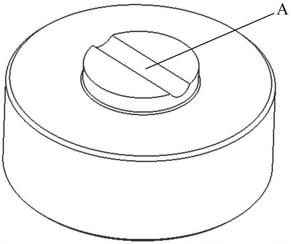
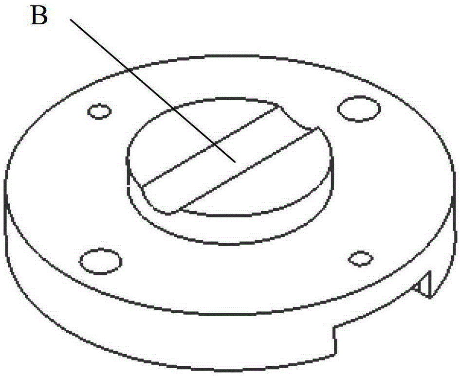
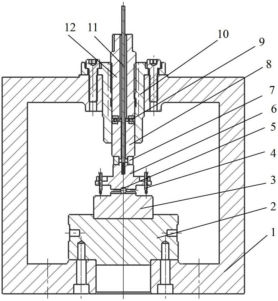
[0022] The test device for the characteristics of the joint surface of the ball and the raceway includes an upper test piece 6 and a lower test piece 3, each of which is provided with a semi-cylindrical raceway, and the upper test piece 6 and the lower test piece The less semi-cylindrical raceways on the top 3 are placed perpendicular to each other, the ball 5 is placed between the less semi-cylindrical raceways of the upper test piece 6 and the lower test piece 3, and the raceways pass through the upper test piece 6 and the displacement sensor 4 and the force sensor 7 connect.

[0023] The upper test piece 6 and the lower test piece 3 are cylindrical and arranged coaxially. A few semi-cylindrical raceways are arranged in the middle of the upper test piece 6 and the lower test piece 3, and both sides are symmetrical.

[0024] A load...


PUM


Abstract

The test device for the characteristics of the joint surface of the ball and the raceway includes two semi-cylindrical raceways placed perpendicularly to each other, balls are placed in the raceway, the raceway is set on the test piece, and the test piece is connected to the displacement sensor and the force sensor. The test piece includes an upper test piece and a lower test piece. The upper and lower test pieces are cylindrical and coaxially arranged. Two less semi-cylindrical raceways are respectively arranged in the middle of the upper test piece and the lower test piece. The displacement sensor And the force sensor is connected with the upper test piece. The invention constrains the movement of the balls by placing the two raceways perpendicular to each other, which solves the problem that the balls are difficult to locate during the test, so that the characteristic data of the joint surface between the balls and the raceways can be obtained. The invention can not only provide a basis for analyzing the characteristics of the joint part of the guide rail, but also has important significance for evaluating the correctness of the characteristic model of the joint surface formed between the ball and the raceway.

Description

technical field [0001] The invention belongs to the technical field of mechanical design and manufacture, and in particular relates to a test device for the characteristics of the joint surface of a ball and a raceway. Background technique [0002] The rolling linear guideway pair is to place rolling elements (balls or rollers) between the guide rail block and the guide rail bar (supporting guide rail), so as to realize the extremely low (rolling) friction transmission between the guide rail block and the guide rail bar, so the rolling linear guide rail pair is widely used. It is used in CNC equipment such as CNC machine tools and robots, and is the main functional component for low-friction feed of moving parts in CNC equipment. The part between the guide rail block and the guide rail bar is called the joint of the rolling linear guide rail. The stiffness of the joint of the rolling linear guide directly affects the static and dynamic performance of the machine tool struct...

Claims


Application Information

Patent Timeline
Patent Type & Authority Patents(China)
IPC IPC(8): G01M13/00
Inventor 张广鹏杨庆超张月黄玉美
Owner SUZHOU FURUTA AUTOMATION TECH
Why Eureka
Try Eureka